TL;DR
The previous article analyzed the algorithm and model structure of DeepSeek-V4, "DeepSeek-V4 Detailed Analysis (1): Algorithm and Model Structure." Next, we analyze Chapter 3 of the technical report and infrastructure-related content. Due to its length, this will be split into several articles. This one focuses specifically on MegaMoE. By carefully overlapping communication and computation latency, MegaMoE achieves an overall performance improvement of 1.5x~1.9x. Below are the test results for DeepSeek-V4-Pro under different batch sizes:
1. Overview
MoE can be accelerated through Expert Parallelism (EP). However, EP requires complex inter-node communication and places significant demands on interconnect bandwidth and latency. To alleviate the communication bottleneck in EP and achieve higher end-to-end performance with lower interconnect bandwidth requirements, the DeepSeek team proposed a fine-grained EP scheme. This scheme fuses communication and computation into a single pipelined kernel to achieve overlap between communication and computation. Regarding fine-grained overlap, ByteDance also has work like COMMET; for details, refer to "A Discussion on ByteDance's COMET, Another Fine-Grained MoE Communication and Computation Overlap Scheme."
1.1 Communication Latency Hiding Analysis
In MoE layers, communication latency can be effectively hidden behind computation. As shown in the figure, in the DeepSeek-V4 series, each MoE layer can be primarily decomposed into four stages: two communication-intensive stages, Dispatch and Combine, and two computation-intensive stages, Linear-1 and Linear-2.
Performance analysis shows that within a single MoE layer, the total communication time is less than the total computation time. Therefore, after fusing communication and computation into a unified pipeline, computation remains the primary bottleneck. This means the system can tolerate lower interconnect bandwidth without degrading end-to-end performance.
1.2 Fine-Grained EP Scheme
To further reduce interconnect bandwidth requirements and amplify the benefits of overlap, the authors introduced a finer-grained expert partitioning scheme. Inspired by many related works (FlashMoE, COMMET), the authors schedule experts in batches, referred to as "waves." Each wave consists of a small subset of experts. Once all experts within a wave have completed their communication, computation can begin immediately without waiting for other experts. In a steady state, the computation of the current wave, the token transmission for the next wave, and the result sending of completed experts all proceed simultaneously, as shown in the figure above. This forms a fine-grained pipeline among experts, keeping computation and communication continuous throughout the wave processing. Wave-based scheduling improves performance in extreme cases, such as the rollout process in Reinforcement Learning (RL), which often encounters long-tail small batches.
The authors validated this fine-grained EP scheme on both NVIDIA GPU and HUAWEI Ascend NPU platforms. Compared to a non-fused baseline, it achieves a 1.50 ~ 1.73x speedup on general inference workloads and up to 1.96x in latency-sensitive scenarios (e.g., RL rollout and high-speed agent services). The authors have open-sourced the CUDA-based MegaKernel implementation, named MegaMoE, as a component of DeepGEMM. For specific code, refer to DeepGEMM's PR304 and PR316.
2. Legacy EP Implementation
2.1 EP Computation and Communication Flow
For DeepSeek's MoE routing algorithm, refer to "Detailed Discussion on the Development of DeepSeek MoE Technologies." The dispatch and combine operations in EP communication involve cross-node NVLink or RDMA communication. The traditional approach executes communication and computation as separate, serial kernels. Consequently, NVLink bandwidth utilization is low, and SM utilization is also low while waiting for communication. For the implementation of DeepEPv2 and the use of the NCCL Gin backend, refer to the following articles:
- NCCL Gin & Symmetric Memory
- DeepEPv2 Analysis (1)
- DeepEPv2 Analysis (2) - EP Overview
- DeepEPv2 Analysis (3) - EP Direct Dispatch/Combine Kernel
- DeepEPv2 Analysis (4) - EP Hybrid Dispatch/Combine Kernel
Before analyzing the Legacy EP, let's supplement the Expert FFN computation.
Expert FFN Computation
Here we supplement the FFN computation within an Expert. Modern LLM models largely adopt the SwiGLU method from Noam Shazeer's 2020 paper GLU Variants Improve Transformer. It uses the Swish (also known as SiLU, Sigmoid-weighted Linear Unit) activation function.
Here is a learnable or fixed hyperparameter (typically 1). When , the formula becomes:

Combining the idea of GLU with the Swish activation function, the SwiGLU computation proceeds as follows:
Input a vector and feed it simultaneously into two different linear layers (or one large linear layer that is then split in half).
- The first linear transformation (also called up-projection):
- The second linear transformation (also called gate-projection):
Then pass the result of the second linear transformation through the Swish activation function to obtain the "gate value".

Finally, multiply the result of the first linear transformation element-wise with the gate value .
The final formula for SwiGLU:

The FFN computation using SwiGLU is as follows:

At the concrete computation level, the code is shown below:
w1 = Linear(dim, inter_dim, dtype=dtype)  # gate projection
w2 = Linear(dim, inter_dim, dtype=dtype)  # up projection
w3 = Linear(inter_dim, dim, dtype=dtype)  # down projection
swiglu_limit = swiglu_limit  # activation value clipping threshold

gate = self.w1(x).float()  # gate branch
up = self.w2(x).float()    # up projection branch

if self.swiglu_limit > 0:
    # Clip activation values to prevent numerical explosion
    up = torch.clamp(up, min=-self.swiglu_limit, max=self.swiglu_limit)
    gate = torch.clamp(gate, max=self.swiglu_limit)

x = F.silu(gate) * up  # SwiGLU: SiLU(gate) * up

if weights is not None:
    x = weights * x  # Multiply by routing weights

return self.w3(x.to(dtype))  # Down-project back to original dimension
Typically during computation, we concatenate the gate and up weights together, which is what the DeepSeek paper refers to as L1. The final down-projection is the second linear layer L2, as shown in the figure below:
⚠️ Note: gate and up can also be stored in an interleaved manner. Combined with Swap AB output, the SwiGLU computation can be performed directly. MegaMoE uses the interleaved approach. We will analyze this in detail in subsequent chapters.
2.2 Legacy EP Implementation
Prior to this, under the EP parallel mode, the execution of the MoE layer consisted of five serial steps: dispatch → linear1 → SwiGLU → linear2 → combine. We can see the flow of the run_baseline() function as follows:
Phase 1: [EP Dispatch] → Distribute tokens across ranks
Route the tokens of the current rank (x is an (fp8_data, sf) tuple) according to topk_idx, sending them to the target rank responsible for the corresponding expert via NVLink all-to-all. Here, ep_buffer is created through the DeepEP library.
recv_x, _, recv_topk_weights, handle, _ = ep_buffer.dispatch( x, topk_idx=topk_idx, topk_weights=topk_weights, num_experts=num_experts, expert_alignment=alignment, do_cpu_sync=False, do_handle_copy=False, do_expand=True, use_tma_aligned_col_major_sf=True)
Phase 2: [L1 Grouped GEMM] → Input projection (gate + up)
Perform grouped matrix multiplication on the received tokens by expert, computing l1_y = recv_x @ l1_weights^T.
n = recv_x[0].size(0)l1_y = torch.empty((n, intermediate_hidden * 2), dtype=torch.bfloat16, device='cuda')deep_gemm.m_grouped_fp8_fp4_gemm_nt_contiguous( recv_x, l1_weights, l1_y, handle.psum_num_recv_tokens_per_expert, use_psum_layout=True, recipe=(1, 1, 32))
Phase 3: [SwiGLU Activation + TopK Weighting + Quantization]
This is a fused kernel (provided by tilelang) that accomplishes four tasks within a single kernel: SwiGLU activation → Clamp truncation → Multiply by TopK weights (subsequent combine only needs pure addition) → Quantize back to FP8.
l1_y = tilelang_ops.swiglu_apply_weight_to_fp8(
    x=l1_y,                                                  # [gate | up] concatenated input
    topk_weights=recv_topk_weights,                          # per-token routing weights
    avail_tokens=handle.psum_num_recv_tokens_per_expert[-1], # actual number of valid tokens
    num_per_channels=32,                                     # SF (scale-factor) grouping granularity (=32)
    use_col_major_scales=True,                               # whether SF is column-major
    round_scale=True,                                        # when True, round SF up to the nearest power of 2
    ue8m0_scale=True,                                        # whether SF is in UE8M0 format
    output_bf16=False,                                       # whether to also output BF16
    clamp_value=args.activation_clamp,                       # clamp threshold
    fast_math=bool(args.fast_math)                           # fast-math
)
Phase 4: [L2 Grouped GEMM] → Output projection
Compute l2_y = l1_y @ l2_weights^T, projecting the intermediate activations back to the hidden dimension.
l2_y = torch.empty((n, hidden), dtype=torch.bfloat16, device='cuda')deep_gemm.m_grouped_fp8_fp4_gemm_nt_contiguous( l1_y, l2_weights, l2_y, handle.psum_num_recv_tokens_per_expert, use_psum_layout=True, recipe=(1, 1, 32))
Phase 5: [EP Combine] → Aggregate back to original tokens
Send the weighted results scattered across ranks back to the rank of the original token via a reverse all-to-all based on the source information recorded in the handle, and then reduce the k expert results for the same original token.
return ep_buffer.combine(l2_y, handle=handle)[0]
3. MegaMoE Implementation
3.1 Overall Architecture
MegaMoE fuses five operations—EP Dispatch, Linear1 (Gate/Up), SwiGLU, Linear2 (Down), and EP Combine—into a single CUDA Kernel, achieving better performance through communication and computation overlap. It also uses FP8 x FP4 mixed-precision GEMM.
Function Input/Output Layout
Input for each rank:
Pre-transformed expert weights:
Overlap Method and Warp Function Division
The diagram from the paper is as follows:
So what is Expert Wave? First, in the Dispatch phase, the original input places tokens generated by each rank into the input_buffer, with an additional input_tok_idx_buffer for expert indexing. Let's use a simple example with Rank=2, a total of 6 experts evenly distributed across each rank (3 experts each), and topk=4.
After dispatch processing, logically, the L1 pool arranges tokens with the local expert as the primary order and places them into corresponding slots. Therefore, the entire pipeline can be split into multiple waves along this dimension. For example:
- Expert Wave 1 processes MoE computation related to Expert 0
- Expert Wave 2 processes MoE computation related to Expert 1
- Expert Wave 3 processes MoE computation related to Expert 2
This approach allows overlapping across multiple Expert Waves, hiding the time required for communication. Of course, this is a very simple example; the actual processing schedules by blocks, which we will analyze in detail in subsequent chapters. Next, let's break down a single wave. The computation flow of a single Expert wave is divided into 5 stages:
- Stage 0 — EP Dispatch: Expert token counting → Global aggregation → NVLink Pull → TMA Store
- Stage 1 — Linear1+SwiGLU: Wave-based scheduling → Swap AB UMMA → UTCCP transpose → TMEM_LOAD interleaved Gate/Up → SwiGLU → FP8 Cast
- Stage 2 — Linear2: L2 arrival mask spin-wait → Down projection GEMM
- Stage 3 — L2 Epilogue: TMEM→BF16→NVLink remote write to Combine Buffer
- Stage 4 — Combine: Double-buffered Top-k load → Float accumulation → TMA Store final output
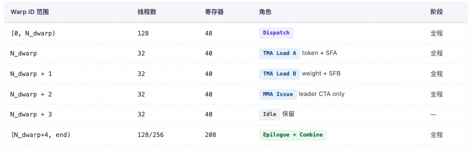
To fully integrate these stages into a single persistent Kernel, we need to use WarpSpecialization for task division, combined with a fine-grained Barrier mechanism to achieve computation and communication overlap. Refer to the source file: deep_gemm/include/deep_gemm/impls/sm100_fp8_fp4_mega_moe.cuh. The specific division is as follows:
The detailed flowchart based on Warp expansion is shown below:
This diagram marks how different warps coordinate through barriers and counters. Here, we provide a brief introduction, with detailed explanations in subsequent chapters.
Dispatch Warp
The Dispatch Warp handles the entire MoE all-to-all dispatch: counting expert hits, reporting expert_send_count, writing remote topk indices, pulling token data / SF / weights back to the L1 pool via NVLink + TMA, and finally cleaning up the workspace while coordinating resource release with the epilogue. The Dispatch warp goes through 6 stages in the persistent kernel, connected by three levels of barriers: intra-SM named barrier, grid_sync, and nvlink_barrier. The entire process is as follows:
-
1️⃣ Count the number of tokens sent from this SM to expert i: The specific approach is to traverse all tokens in parallel, with each SM responsible for a portion. It uses
atomicAddin smem to count the number of tokens for each expert within this SM. -
2️⃣ Global
send_count: This step is clever. It usesatomicAddto write the expert send countexpert_send_count[i]to the global workspace. Note that this global counter acts like a ticket dispenser. For example, if the current value is A1, after SM 1 performsatomicAdd, the counter updates to A1 + sm1_count, and the old value A1 is returned. SM 1 then knows that the interval [A1, A1 + sm0_count) is the data segment to receive, with A1 as the starting offset in the remote expert slot. Subsequently, SM 2'satomicAddwill return A1 + sm1_count, which serves as SM 1's starting offset in the remote expert slot. -
3️⃣ Write remote topk idx: Based on the starting offset from the previous step, the local token's
topk_idxcan be written to the remote location. Why write the topk idx to the remote location in step 3? Because the sending rank knows which token was sent to which expert, but the receiving rank that owns the expert is the entity that will perform the subsequent pull. It needs to directly read its local workspace to find the source index for each slot, avoiding a reverse NVLink lookup during the pull. -
4️⃣ SM0 aggregation: After
grid_sync,expert_send_count[i]from step 2 is already the final aggregated value for this rank (all kNumSMs contributors have joined). Cross-rank writing only needs to be done once by SM0, which updates the receiver'srecv_count, a 2D array of [rank, expert_idx]. It also performs oneatomicAddto update the remoteexpert_recv_count_sum, which represents the total number of tokens for that expert sent from all ranks. In the subsequent scheduler, thefetch_expert_recv_countfunction performs anld_volatilespin-wait loop for each expert. When all tokens have arrived, it triggers block dispatch scheduling and subsequent GEMM operations. -
5️⃣ Pull tokens: Pull the token data (FP8 weights + scale factor + topk weights) from other ranks that hit the local expert back to the local L1 token pool, and set
l1_arrive_cntto trigger TMA-Producer A consumption. -
6️⃣ Clean up workspace: This is memory cleanup performed during the final completion phase.
2️⃣ Global send_count: This step is quite clever. It uses atomicAdd to write the expert send count expert_send_count[i] to the global workspace. Note that this global counter acts like a ticket dispenser. For example, if the current value is A1, after SM 1 performs atomicAdd, the counter updates to A1 + sm1_count and returns the old value A1. SM 1 then knows that the interval [A1, A1 + sm0_count) is its segment for receiving data, with A1 serving as the starting offset on the remote expert slot. Subsequently, SM 2's atomicAdd will return A1 + sm1_count, which it uses as its starting offset on the remote expert slot.
3️⃣ Write remote topk_idx: Based on the starting offset from the previous step, the topk_idx of the local token is written to the remote location. Why is it necessary to write topk_idx to the remote side in the third step? Because the sending rank knows which token it sent to which expert, but the receiving rank, which owns the expert, is the entity that will execute the subsequent pull. It needs to be able to read the local workspace directly to find the source index for each slot, avoiding the need for a reverse NVLink lookup during the pull.
4️⃣ SM0 Aggregation: After grid_sync completes, expert_send_count[i] from step 2 is the final aggregated value for this rank (all kNumSMs contributors have joined). Writing across ranks only needs to be done once by SM 0. It updates the receiver's recv_count, which is a 2D array of [rank, expert_idx]. It also performs an atomicAdd to update the remote expert_recv_count_sum, which represents the total number of tokens for that expert sent from all ranks. In the subsequent scheduler, the fetch_expert_recv_count function executes a ld_volatile spin loop for each expert. When all tokens have arrived, it triggers block dispatch scheduling and initiates the subsequent GEMM computation.
5️⃣ Pull tokens: Pull the main body of tokens (FP8 weights + scale factor + topk weights) that hit the local expert from other ranks back into the local L1 token pool. Simultaneously, it sets l1_arrive_cnt to trigger consumption by TMA-Producer A.
6️⃣ Clean up workspace: This is the memory cleanup work performed during the final completion phase.
TMA-Producer A Warp
During the GEMM phase of the MoE kernel, this warp acts as the producer that loads activations and their scale factors. It is driven by the scheduler via scheduler.for_each_block.
It handles the activation data loading for both the L1 GEMM and L2 GEMM:
- The L1 phase is triggered by waiting for
l1_arrive_cnt, which is updated by the Dispatch Warp. - The L2 phase is triggered by waiting for
l2_arrive_mask, which is updated by the L1 Epilogue warp.
Once triggered, it cooperates with TMA-Producer B and the MMA Warp to iterate over the K dimension and complete the data loading for the GEMM computation. It then notifies the MMA Warp that loading is complete via full_barriers[stage_idx]. The MMA Warp can also notify TMA-Producer A to proceed with the next round of loading via empty_barriers[stage_idx].
TMA-Producer B Warp
The TMA Load B warp is the weight producer for the MoE kernel's GEMM. It does not need to wait and directly loads weights along the K dimension using TMA. It coordinates with TMA-Producer A and the MMA Warp to advance along the K dimension using full_barriers[stage_idx] and empty_barriers[stage_idx]. After the computation for the current phase is complete, it switches to the L2 phase to continue weight loading.
MMA Warp
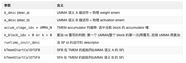
The MMA Issue warp is the computational heart of the entire kernel. It consumes A/B data and SF from shared memory (smem), moves the SF to Tensor Memory (TMEM) via UTCCP, and issues the SM1002-CTA UMMA instruction. This allows two CTAs to jointly complete the computation of one GEMM tile, with the accumulated results remaining directly in TMEM for the epilogue warp to read. There are some "Swap AB" techniques involved here, which will be detailed in a later chapter.
The results in the TMEM accumulator use a double-buffering mechanism and coordinate with the Epilogue Warp via tmem_full_barriers and tmem_empty_barriers.
Epilogue Warp
This is also a very complex warp to handle, covering three stages:
L1 Epilogue
This mainly includes SwiGLU + FP8 quantization + TMA store + UE8M0 SF write steps. L1 = post-processing of the results from the first stage GEMM (gate + up projection). It first loads the top-k weights into register cache, then loads the interleaved gate/up values from TMEM (TMEM_LOAD), and performs the SwiGLU computation: silu(gate) × up × weight. It then performs amax processing within the warp. This involves per-lane amax calculation, warp reduce, and cross-warp reduce, followed by quantization to FP8 E4M3, storing the SF according to the UE8M0 scheme.
Finally, it writes the result to tensor_map_l1_output (the GMEM view of l2_token_buffer) via TMA store. It then uses an atomic bitwise operation (red_or_rel_gpu(l2_arrival_mask)) to signal "this N sub-block is ready" for TMA-Producer A to load the block for the L2 phase.
L2 Epilogue
This mainly includes TMEM → BF16 → STSM → NVLink remote write steps. L2 = post-processing of the results from the second stage GEMM (down projection). It first reads the completed L2 GEMM data from the TMEM accumulator, converts it to BF16 format, and writes it to smem_cd_l2 via STSM. Then, based on token_src_metadata, it determines the remote rank/token/topk position for each row and writes the result directly to the remote combine_token_buffer[topk_idx][token_idx] via NVLink (sym_buffer.map).
Combine Phase
Goal of the Combine phase: Each token dispatched by the local rank has kNumTopk result copies (computed by different remote experts). These need to be reduced into a single result and written back to the user's y. First, it requires an nvlink_barrier to wait for all ranks to complete their L2 writes. Then, it signals that the Dispatch warp can begin cleanup. Next, for each token, it reads the top-k slot indices, performs FP32 accumulation in chunks, casts the final result back to BF16 format, stores it in SMEM, and finally calls TMA Store to output the final y.
We have provided a brief overview of the workflow for these 5 types of warps within a single Expert Wave. However, some details are still missing, such as how Expert Waves are partitioned and how block tasks are assigned. Therefore, we will first analyze the Scheduler below, followed by an analysis of the relevant control counters and the buffers used for inter-warp coordination.
3.3 Scheduler
The Scheduler is a critical component of the entire algorithm. The code is located in deep_gemm/include/deep_gemm/scheduler/mega_moe.cuh. The entire scheduling is structured as a three-level state machine, from outer to inner:
-
Wave: Experts are packed according to
kNumExpertsPerWave. -
Block:
expert,m_block,n_block. -
Phase:
Linear1→Linear2. -
Wave: Experts are packed according to
kNumExpertsPerWave. -
Block:
expert,m_block,n_block. -
Phase:
Linear1→Linear2.
When executing GEMM, the processing of kNumExpertPerWave experts is first bundled into a single Wave. Within each Wave, each expert is aligned according to the BLOCK_M size, and then blocked matrix multiplication is performed. Since MoE FFN computation involves two GEMM operations, the Phase is responsible for switching between Linear1↔Linear2. All L1 blocks within a wave must be completed before uniformly switching to L2. Within a single Phase, the Block is responsible for block-cyclic dispatch across SMs.
3.2.1 Heuristic Configuration
Before introducing the scheduler, a heuristic configuration is required for parameters such as the amount of data to be processed per Wave and the Block size. Source path: csrc/jit_kernels/heuristics/mega_moe.hpp. Based on runtime inputs (num_ranks/num_experts/hidden/…), it derives a MegaMoEConfig that satisfies the triple constraints of correctness + shared memory limit + SM utilization, which is then passed to sm100_fp8_fp4_mega_moe.hpp for JIT source template instantiation. Its external API is as follows:
The entire call chain is as follows:
apis/mega.hpp      │ (Python layer passes shape / rank info)      ▼get_mega_moe_config()   ← Top level
  ├── get_block_config_for_mega_moe()           ← Selects BLOCK_M, etc.
  ├── SM100ArchSpec::get_sf_uttcp_aligned_block_sizes()  ← Selects SF blocks
  ├── layout::get_num_max_pool_tokens()         ← Selects Pool capacity
  ├── get_num_experts_per_wave_for_mega_moe()   ← Selects wave granularity
  └── get_pipeline_config_for_mega_moe()        ← Derives num_stages + smem
      │ (Returns MegaMoEConfig)
      ▼impls/sm100_fp8_fp4_mega_moe.hpp              ← JIT code generation
Some internal field definitions are as follows:
3.2.1.1 Block Size Selection
The function for selecting the BLOCK_M parameter is:
static std::tuple<int, int, int, int> get_block_config_for_mega_moe( const int& num_ranks, const int& num_experts, const int& num_max_tokens_per_rank, const int& num_topk, const int& num_tokens);
Its input parameters are:
Returns std::tuple<cluster_size, block_m, store_block_m, num_epilogue_warpgroups * 128>:
-
cluster_size: always 2 (2-CTA cluster) -
block_m: selected from -
store_block_m: M granularity for epilogue TMA store -
The last element is
num_epilogue_warpgroups * 128, i.e.,num_epilogue_threads
cluster_size: always 2 (2-CTA cluster)
block_m: selected from
store_block_m: M granularity for epilogue TMA store
The last element is num_epilogue_warpgroups * 128, i.e., num_epilogue_threads
The core algorithm dispatches based on the token-per-expert tier:
float num_expected_tokens_per_expert = static_cast<float>(num_tokens) * num_ranks * num_topk / num_experts;
The formula explanation is as follows:
-
Upper bound on total tokens received by this rank per iteration ≈
num_tokens * num_ranks(all ranks send their tokens to the current rank) -
Each token triggers
num_topkexpert routing decisions -
Routing is evenly distributed across
num_expertsexperts -
This yields the expected number of tokens assigned to each expert
Upper bound on total tokens received by this rank per iteration ≈ num_tokens * num_ranks (all ranks send their tokens to the current rank)
Each token triggers num_topk expert routing decisions
Routing is evenly distributed across num_experts experts
This yields the expected number of tokens assigned to each expert
Since a 2-CTA cluster is used for GEMM, cluster_size is always 2. Other values are selected from 6 tiers:
-
store_block_m ≤ block_m: Allows the epilogue to perform multiple TMA stores, overlapping the M direction with TMEM reads -
Small
BLOCK_Muses 2 warpgroups (256 epilogue threads): The epilogue workload has "many thin tiles, each light", using two warp groups to pipeline multiple stores in parallel -
BLOCK_M=64tier uses 1 warpgroup: The tile size is just right; a single group is sufficient to hide latency, saving dispatch/combine barrier count in smem
store_block_m ≤ block_m: Allows the epilogue to perform multiple TMA stores, overlapping the M direction with TMEM reads
Small BLOCK_M uses 2 warpgroups (256 epilogue threads): The epilogue workload has "many thin tiles, each light", using two warp groups to pipeline multiple stores in parallel
BLOCK_M=64 tier uses 1 warpgroup: The tile size is just right; a single group is sufficient to hide latency, saving dispatch/combine barrier count in smem
3.2.1.2 Pool Capacity
During the dispatch phase, each rank receives tokens from all ranks. These tokens are grouped by expert and stored in a contiguous shared pool (all local experts share a single buffer segment), with each expert occupying a contiguous interval. This allows MMA warps to scan by BLOCK_M chunks just like a regular GEMM. Therefore, the pool capacity must satisfy two conditions:
-
It must be able to accommodate all tokens actually received in the worst case.
-
The starting address of each expert must be aligned to
BLOCK_M(otherwise TMA / UMMA addressing will be incorrect), and this alignment must hold for all candidateBLOCK_Mvalues.
It must be able to accommodate all tokens actually received in the worst case.
The starting address of each expert must be aligned to BLOCK_M (otherwise TMA / UMMA addressing will be incorrect), and this alignment must hold for all candidate BLOCK_M values.
The complete calculation formula is as follows:

-
=
num_ranks -
=
num_max_tokens_per_rank -
=
num_topk -
=
num_experts_per_rank
= num_ranks
= num_max_tokens_per_rank
= num_topk
= num_experts_per_rank
Let's explain in detail. The tokens that this rank can receive originate only from "the input tokens of each rank across the entire network". In the worst case, every rank routes all its tokens to the experts on this rank, so the upper bound is:

This is the upper bound on the number of tokens (not multiplied by top-k). A single token is replicated into num_topk copies and sent to different experts. However:
-
If
num_topk ≤ num_experts_per_rank: In the worst case, all top-k copies land on experts within this rank →num_topk. -
If
num_topk > num_experts_per_rank: Since a token's top-k selections will not choose duplicate experts (differentexpert_idxvalues), it can select at mostnum_experts_per_rankexperts on this rank, meaning each expert receives at most 1 copy → capped atnum_experts_per_rank.
If num_topk ≤ num_experts_per_rank: In the worst case, all top-k copies land on experts within this rank → num_topk.
If num_topk > num_experts_per_rank: Since a token's top-k selections will not choose duplicate experts (different expert_idx values), it can select at most num_experts_per_rank experts on this rank, meaning each expert receives at most 1 copy → capped at num_experts_per_rank.
Therefore, min(num_topk, num_experts_per_rank) is taken as the maximum number of copies a single token can have on this rank.
const auto num_max_experts_per_token = math::constexpr_min(num_topk, num_experts_per_rank);
Multiply the two:

This represents the total number of tokens in the extreme case where "all tokens from all ranks hit this rank, and each token is replicated as many times as possible on this rank." This is the upper bound of the real data in the pool.
Then, considering alignment to BLOCK_M, we add + num_experts_per_rank * (kMaxCandidateBlockM - 1).
Why is padding needed?
The starting position of each expert in the pool must be aligned to BLOCK_M (for TMA/UMMA addressing and SF layout). The common practice is to pad the end of each expert to the next BLOCK_M boundary.
-
In the worst case for a single expert,
BLOCK_M - 1positions are added (when the actual number of tokens is exactly one more than a multiple ofBLOCK_M). -
This rank has
num_experts_per_rankexperts, so the worst-case total padding is:num_experts_per_rank × (BLOCK_M - 1).
Why use kMaxCandidateBlockM?
BLOCK_M is determined at JIT runtime (selected from the candidates ). The pool size must be reserved once and cannot change with different BLOCK_M values. Therefore, we take the largest candidate, 192, to ensure it is sufficient for any choice:

This is a conservative upper bound that "covers all possible BLOCK_M values."
Why is padding needed?
The starting position of each expert in the pool must be aligned to BLOCK_M (for TMA/UMMA addressing and SF layout). The common practice is to pad the end of each expert to the next BLOCK_M boundary.
-
In the worst case for a single expert,
BLOCK_M - 1positions are added (when the actual number of tokens is exactly one more than a multiple ofBLOCK_M). -
This rank has
num_experts_per_rankexperts, so the worst-case total padding is:num_experts_per_rank × (BLOCK_M - 1).
In the worst case for a single expert, BLOCK_M - 1 positions are added (when the actual number of tokens is exactly one more than a multiple of BLOCK_M).
This rank has num_experts_per_rank experts, so the worst-case total padding is: num_experts_per_rank × (BLOCK_M - 1).
Why use kMaxCandidateBlockM?
BLOCK_M is determined at JIT runtime (selected from the candidates ). The pool size must be reserved once and cannot change with different BLOCK_M values. Therefore, we take the largest candidate, 192, to ensure it is sufficient for any choice:
This is a conservative upper bound that "covers all possible BLOCK_M values."
Finally, the "real upper bound + padding upper bound" calculated above needs to be further aligned up to kLCMCandidateBlockM = 384.
return math::constexpr_align( num_max_recv_tokens * num_max_experts_per_token + num_experts_per_rank * (kMaxCandidateBlockM - 1), static_cast<T>(kLCMCandidateBlockM));
kLCMCandidateBlockM = 384 is the least common multiple of all candidate BLOCK_M values, ensuring the total pool capacity is divisible by any candidate BLOCK_M. This way, no matter which BLOCK_M the heuristic ultimately selects, the number of blocks in the pool is an integer, avoiding the trouble of "splitting an incomplete block."
For example, let num_ranks=8, num_max_tokens_per_rank=256, num_topk=8, num_experts_per_rank=32:
3.2.1.3 Expert Wave Granularity
This part determines, within a wave (scheduling wave), how many local experts each rank should process concurrently to fully utilize all SMs without amplifying load imbalance.
First, estimate the "expected number of tokens per expert."
float expected_tokens_per_expert = static_cast<float>(num_tokens) * num_topk / num_experts_per_rank;
num_tokens * num_topk: The total number of tokens this rank needs to send to local experts (each token is replicated top-k times), divided by num_experts_per_rank: The number of tokens each local expert receives assuming perfectly uniform routing. This is the "paper average," and all subsequent load estimates are based on it.
In sparse extreme cases, when the average is less than 1 token per expert (e.g., very few tokens and many experts), scheduling waves is wasteful. Simply put all local experts into a single wave and compute them all at once to avoid idling.
if (expected_tokens_per_expert < 1) { return num_experts_per_rank;}
However, actual routing is not uniform: some hot experts receive far more tokens than the average, while cold experts receive very few. If we only calculate the number of blocks based on the "average," hot experts will cause tail latency. Therefore, we amplify the target workload by a factor of 2, i.e., kImbalanceFactor = 2 (effectively compensating for the capacity lost to cold experts being undercounted), leaving redundancy so hot experts can also fully utilize the SMs.
Next, estimate the number of L1 blocks for a single expert under uniform routing.
const int num_m_blocks = ceil_div(
    static_cast<int>(std::ceil(expected_tokens_per_expert)),
    block_m);
const int num_n_blocks = (2 * intermediate_hidden) / block_n;  // L1 N is 2I (gate||up)
const int num_l1_blocks_per_expert = num_m_blocks * num_n_blocks;
-
num_m_blocks: Split the M direction byblock_mto get the number of M-blocks each expert needs to compute. -
num_n_blocks: The output width of Linear1 is2 * intermediate_hidden(gate and up concatenated), split byblock_n. -
Multiply them to get the total number of (m_block × n_block) a single expert needs to compute in the L1 phase.
This quantity represents "how many SMs a single expert can feed." Then, the lower bound for the number of experts per wave can be found using the following formula. The goal is: if the value is too large, the number of waves decreases and the scheduling granularity becomes too coarse; if too small, some SMs will be starved. So, we take the value that is "just enough to fully utilize the SMs."

Then, cap it with num_experts_per_rank to avoid exceeding the actual number of experts on this rank.
num_experts_per_wave = std::min(num_experts_per_wave, num_experts_per_rank);
Finally, round up to a factor of num_experts_per_rank.
while (num_experts_per_wave < num_experts_per_rank and num_experts_per_rank % num_experts_per_wave != 0) ++num_experts_per_wave;
The scheduler requires that each wave processes the same number of experts (otherwise, the last wave would be an irregular tail, triggering a static assertion in the scheduler). Therefore, we keep incrementing by 1 until it divides num_experts_per_rank evenly. For example, num_experts_per_rank = 16:
-
If the formula yields 5 → round up to 8 (because 16%5≠0, 16%6≠0, 16%7≠0, 16%8=0).
-
If the formula yields 3 → round up to 4.
-
If the formula yields 9 → round up to 16.
If the formula yields 5 → round up to 8 (because 16%5≠0, 16%6≠0, 16%7≠0, 16%8=0).
If the formula yields 3 → round up to 4.
If the formula yields 9 → round up to 16.
Assume num_tokens=1024, num_topk=8, num_experts_per_rank=32, intermediate_hidden=2048, block_m=128, block_n=128, num_sms=148:
-
expected_tokens_per_expert = 1024*8/32 = 256(≥1, enters the normal branch) -
num_m_blocks = ceil(256/128) = 2 -
num_n_blocks = 2*2048/128 = 32 -
num_l1_blocks_per_expert = 2*32 = 64 -
num_experts_per_wave = ceil(2*148/64) = ceil(4.625) = 5 -
min(5, 32) = 5 -
Round up to a factor: 5→8 (the nearest factor of 32 that is ≥5)
-
Final
num_experts_per_wave = 8, meaning 32 local experts are divided into 4 waves, with 8 experts per wave. The concurrency is approximately 8×64=512 L1 blocks, providing ~3.5x redundancy for 148 SMs, which is sufficient to absorb routing imbalance.
expected_tokens_per_expert = 1024*8/32 = 256 (≥1, enters the normal branch)
num_m_blocks = ceil(256/128) = 2
num_n_blocks = 2*2048/128 = 32
num_l1_blocks_per_expert = 2*32 = 64
num_experts_per_wave = ceil(2*148/64) = ceil(4.625) = 5
min(5, 32) = 5
Round up to a factor: 5→8 (the nearest factor of 32 that is ≥5)
Final num_experts_per_wave = 8, meaning 32 local experts are divided into 4 waves, with 8 experts per wave. The concurrency is approximately 8×64=512 L1 blocks, providing ~3.5x redundancy for 148 SMs, which is sufficient to absorb routing imbalance.
3.2.1.4 SMEM Distribution and Pipeline Depth Estimation
The question this function answers is: within the shared memory limit of an SM, how many pipeline stages (num_stages) can be opened to maximize the overlap between TMA loads in the K direction and MMA computation? It uses "(total smem − fixed overhead) / single-stage pipeline overhead" and rounds down. The memory allocation in SMEM is as follows:
Fixed Overhead Section
First, the Dispatch area
smem_expert_count_size = align(num_experts * 4, 1024)smem_send_buffers_size = align( Buffer(Data(hidden), num_dispatch_warps, 1).bytes , 1024 )smem_dispatch_size = smem_expert_count_size + smem_send_buffers_size
-
expert_count: oneuint32counter per global expert (counts the number of tokens this SM needs to send during the dispatch phase). Aligned to 1 KB. -
send_buffers: each dispatch warp holds a buffer of sizehidden, used to temporarily store tokens to be sent across ranks (byte count calculated vialayout::Buffer(Data(hidden), num_dispatch_warps, 1)). Aligned to 1 KB.
expert_count: one uint32 counter per global expert (counts the number of tokens this SM needs to send during the dispatch phase). Aligned to 1 KB.
send_buffers: each dispatch warp holds a buffer of size hidden, used to temporarily store tokens to be sent across ranks (byte count calculated via layout::Buffer(Data(hidden), num_dispatch_warps, 1)). Aligned to 1 KB.
Next, the C/D output area
smem_cd_l1 = num_epilogue_warpgroups * store_block_m * (block_n / 2) * kNumTMAStoreStagessmem_cd_l2 = num_epilogue_warpgroups * store_block_m * block_n * sizeof(bf16)smem_cd = max(smem_cd_l1, smem_cd_l2)
The epilogues of L1 and L2 reuse the same segment of smem, so the max of the two is taken:
-
L1 (Linear1 output, after SwiGLU): data type is FP8 (1 byte); SwiGLU merges gate×up to half width →
block_n/2; requires 2 TMA store buffers for double-buffering overlap.- Size = number of warpgroups ×
store_block_m×block_n/2× 1 byte × 2 stages
- Size = number of warpgroups ×
-
L2 (Linear2 output): data type is BF16 (2 bytes), only 1 copy (written directly to the remote end via NVLink).
- Size = number of warpgroups ×
store_block_m×block_n× 2 bytes
- Size = number of warpgroups ×
L1 (Linear1 output, after SwiGLU): data type is FP8 (1 byte); SwiGLU merges gate×up to half width → block_n/2; requires 2 TMA store buffers for double-buffering overlap.
- Size = number of warpgroups ×
store_block_m×block_n/2× 1 byte × 2 stages
Size = number of warpgroups × store_block_m × block_n/2 × 1 byte × 2 stages
L2 (Linear2 output): data type is BF16 (2 bytes), only 1 copy (written directly to the remote end via NVLink).
- Size = number of warpgroups ×
store_block_m×block_n× 2 bytes
Size = number of warpgroups × store_block_m × block_n × 2 bytes
Next is the Amax reduction buffer. When the L1 epilogue performs FP8 quantization, it needs to find the amax (maximum absolute value) across warps. This smem is used for exchanging intermediate results between warps. Each row of each store tile has 4 bytes per epilogue warp.
smem_amax_reduction = store_block_m * num_epilogue_warps * sizeof(float)
Finally, the barrier area
smem_barriers = (num_dispatch_warps + kNumEpilogueStages * 2 + num_epilogue_warps * 2) * 8
Each mbarrier occupies 8 bytes, divided into three categories:
Additionally, a pointer (4 bytes) returned by the TMEM allocator needs to be placed in smem for all epilogue warps to read.
Single-Stage Pipeline Overhead
Each pipeline stage requires a copy of "A tile + B tile + SFA + SFB + 2 barriers" — this is the cost paid for the pipeline to have N stages of concurrency. Key points:
-
A tile: due to 2-CTA multicast, a single CTA only needs to load
load_block_m × block_k = (BLOCK_M/2) × BLOCK_K. The data type is FP8 (1 byte), so there is no additional size multiplier. -
B tile:
block_n × block_k. -
SFA/SFB: according to UTCCP requirements, every 128 elements share 1 scale (UE8M0 packed as
uint32), so calculated based onsf_block_m/sf_block_n, with each slot being 4 bytes. -
2 × 8 bytes: the
full_barrierandempty_barrierfor each stage (producer/consumer dual-barrier protocol).
A tile: due to 2-CTA multicast, a single CTA only needs to load load_block_m × block_k = (BLOCK_M/2) × BLOCK_K. The data type is FP8 (1 byte), so there is no additional size multiplier.
B tile: block_n × block_k.
SFA/SFB: according to UTCCP requirements, every 128 elements share 1 scale (UE8M0 packed as uint32), so calculated based on sf_block_m/sf_block_n, with each slot being 4 bytes.
2 × 8 bytes: the full_barrier and empty_barrier for each stage (producer/consumer dual-barrier protocol).
smem_sfa_per_stage = sf_block_m * 4
smem_sfb_per_stage = sf_block_n * 4
smem_per_stage     = load_block_m * block_k    // A tile (only half remains after multicast)
                   + block_n      * block_k    // B tile (each CTA has the full BLOCK_N)
                   + smem_sfa_per_stage        // SFA (UTCCP aligned, 1 SF group per 128 elements, 4 B)
                   + smem_sfb_per_stage        // SFB
                   + 2 * 8                     // full + empty barrier for this stage
Calculating num_stages
Subtract the fixed overhead from the SMEM capacity to obtain the "available smem" that can be allocated to the pipeline buffer. Divide by the single-stage overhead, and round down to get the maximum number of stages that can be accommodated. Finally, assert that num_stages >= 2 — at least double buffering is required to achieve load↔compute concurrency; otherwise, it degenerates into serial execution.
const int num_stages = (smem_capacity - smem_fixed) / smem_per_stage;DG_HOST_ASSERT(num_stages >= 2);
Assume the common SM100 scenario: smem_capacity = 232 KB, num_experts=256, num_dispatch_warps=4, num_epilogue_warps=8, block_m=128, block_n=128, block_k=128, store_block_m=32, sf_block_m=128, sf_block_n=128, hidden=7168.
First, calculate the fixed region (roughly):
| Item | Approximate Value |
|---|---|
smem_expert_count | align(256·4, 1024) = 1024 B |
smem_send_buffers | align(4·hidden·1B, 1024) ≈ 29 KB |
smem_dispatch | ≈ 30 KB |
smem_cd_l1 | 2·32·64·2 = 8 KB |
smem_cd_l2 | 2·32·128·2 = 16 KB |
smem_cd = max | 16 KB |
smem_barriers | (4 + 4 + 16)·8 = 192 B |
smem_amax | 32·8·4 = 1 KB |
smem_tmem_ptr | 4 B |
smem_fixed | ≈ 47 KB |
| Item | Value |
|---|---|
| A tile | 64·128 = 8 KB |
| B tile | 128·128 = 16 KB |
| SFA | 128·4 = 512 B |
| SFB | 128·4 = 512 B |
| 2 barriers | 16 B |
smem_per_stage | ≈ 25 KB |
Finally: num_stages = (232 - 47) / 25 = 185 / 25 = 7, meaning a 7-stage pipeline is opened. The total occupancy is approximately 47 + 7×25 = 222 KB, which fits within the 232 KB budget, leaving about 10 KB for alignment overhead.
3.2.2 Detailed Scheduling Flow
The wave start expert = align_down(cur_expert, kNumExpertsPerWave), and the wave end expert = get_wave_expert_end_idx(). Assume that the tokens of an expert are split along the M dimension with BLOCK_M=16; the tail that is less than one block is padded to 16 rows, but only valid_m rows are valid.
uint32_t get_current_num_m_blocks() const { return math::ceil_div(current_num_tokens, BLOCK_M); // ceil(num_tokens / 16)}
The total block count formula, where kNumL1BlockNs = L1_SHAPE_N / BLOCK_N, kNumL2BlockNs = L2_SHAPE_N / BLOCK_N.
| Stage | Blocks per Expert |
|---|---|
| L1 (Linear1) | num_m_blocks × kNumL1BlockNs |
| L2 (Linear2) | num_m_blocks × kNumL2BlockNs |
For a wave containing W = kNumExpertsPerWave experts; the L1 blocks of each expert form a 2D table of size num_m_blocks(e) × kNumL1BlockNs. During scheduling, all experts in the entire wave are concatenated head-to-tail in expert order into a 1D address:
The overall scheduling flow is as follows:
Specifically, the BlockPhase structure is as follows:
// Computation phase for the current block
enum class BlockPhase {
    None = 0,      // All tasks have been processed, the outer loop should exit
    Linear1 = 1,   // Current task belongs to MoE layer 1 linear transformation (usually gate/up projection)
    Linear2 = 2    // Current task belongs to MoE layer 2 linear transformation (usually down projection)
};
The state machine of get_next_block is as follows, where block_idx += kNumSMs allows each SM to take the next block in steps of kNumSMs, naturally achieving block-cyclic allocation across SMs:
| SM | block_idx |
|---|---|
| SM 0 | 0, kNumSMs, 2·kNumSMs, ... |
| SM 1 | 1, 1+kNumSMs, ... |
| ... | ... |
// Core state machine: assigns the next block
    CUTLASS_DEVICE cute::tuple<BlockPhase, uint32_t, uint32_t, uint32_t> get_next_block() {
        while (true) {
            // Termination condition: all local experts have been processed.
            if (current_local_expert_idx >= kNumExpertsPerRank)
                break;
            if (next_phase == BlockPhase::Linear1) {
                if (fetch_next_l1_block()) {
                    // Hit L1 block: derive n_block_idx from m_block_idx (N dimension flattened).
                    n_block_idx = block_idx - m_block_idx * kNumL1BlockNs;
                    // Jump to the next candidate block for this SM (block-cyclic stride = kNumSMs).
                    block_idx += kNumSMs;
                    return {BlockPhase::Linear1,
                            current_local_expert_idx, m_block_idx, n_block_idx};
                } else {
                    // All L1 blocks of the current wave have been assigned, switch to L2.
                    next_phase = BlockPhase::Linear2;
                    // Key fallback: reset the expert to the start of the current wave, re-scan to issue L2 blocks.
                    // Use align<..., false> (round down), combined with "-1" to offset the case where
                    // current_local_expert_idx has already passed the wave tail when the fetch loop exits.
                    set_expert_idx(math::align<uint32_t, false>(
                        current_local_expert_idx - 1, kNumExpertsPerWave));
                }
            } else {
                if (fetch_next_l2_block()) {
                    n_block_idx = block_idx - m_block_idx * kNumL2BlockNs;
                    block_idx += kNumSMs;
                    return {BlockPhase::Linear2,
                            current_local_expert_idx, m_block_idx, n_block_idx};
                } else {
                    // All L2 blocks of the current wave have been issued, continue to the next wave from Linear1.
                    // Note: at this point, current_local_expert_idx has been advanced by fetch_next_l2_block's advance_expert_idx
                    // to "past the end of the current wave", which is exactly the start of the next wave.
                    next_phase = BlockPhase::Linear1;
                }
            }
        }
        // All processing done, return None to let the outer loop exit.
        return {BlockPhase::None, 0, 0, 0};
    }
These scheduler modules are then exposed to the kernel via a single for_each_block(func) interface. Each Warp obtains tasks through the scheduler, reducing the complexity of the upper-level code.
3.3 Buffer Layout
Before introducing the detailed execution flow, let's first look at how its Buffers are partitioned across multiple GPUs. MegaMoE uses NVLink Symmetric Memory. The entire Layout is divided into two parts: Workspace and Buffer. The specific code is defined in csrc/apis/mega.hpp and deep_gemm/include/deep_gemm/layout/mega_moe.cuh.
3.3.1 Workspace
The Layout::Workspace object defines the memory structure layout of all cross-warp, cross-CTA, and cross-rank control plane data within the MegaMoE kernel on a single symmetric buffer (a multi-GPU shared address space connected via NVLink). It starts from sym_buffer.get_base_ptr() and is divided into segments. It mainly includes the following categories:
Each segment calculates its offset using get_*_ptr(indices), and each getter uses the "tail pointer" of the previous segment as its own starting point. For example, get_expert_recv_count_ptr is derived from get_expert_send_count_ptr(num_experts), and get_l2_arrival_mask_ptr is derived from get_l1_arrival_count_ptr(align(...)). This design means that modifying the size of one segment only requires a change in one place, and the entire chain is automatically realigned. Furthermore, all getters are pure pointer arithmetic, fully expanded at compile time into constant offsets or simple base + const * indices. Device-side calls are equivalent to direct pointer access.
To better understand the state synchronization between multiple warps later, let's analyze these barriers and counters in detail.
First, there are two system-level APIs:
get_num_bytes()
It is the sole entry point on the host side for determining the total allocation size.
get_end_ptr()
Host chain allocation advance_ptr(base, get_num_bytes())
Barriers for Synchronization
get_grid_sync_count_ptr<kIndex>()
kIndex is a compile-time template parameter, ranging from 0 to 3, that selects an independent grid sync counter slot. It points to a uint32_t, where the 32-bit value is split into two parts: the lower bits accumulate the number of SMs that have arrived, and the highest bit 0x80000000 serves as the "completion flag". The grid sync implementation is in /deep_gemm/include/deep_gemm/comm/barrier.cuh, and its workflow is as follows:
- Thread 0 on each SM performs an atomic add: SM 0 writes
0x80000000 - (kNumSMs - 1), while other SMs write1. - Thread 0 on all SMs spins with
ld_acqwaiting for the highest bit to flip, i.e.,(new ^ old) & 0x80000000 != 0.
Invocation timing: The Dispatch calls grid_sync<kDispatchGridSyncIndex = 0> after writing the completion count and source indices. The Epilogue calls grid_sync<kEpilogueGridSyncIndex = 1> after the NVLink write-back completes. The two channels are fully decoupled; the dispatch grid sync does not block the epilogue grid sync.
Interaction with other components: The grid sync serves as a pre/post condition for the NVLink barrier. The nvlink_barrier function can optionally perform a grid sync before and after (controlled by the sync_prologue/sync_epilogue parameters), ensuring all SMs are aligned before cross-rank operations.
get_nvl_barrier_counter_ptr() / get_nvl_barrier_signal_ptr(phase)
Points to a 32-bit integer whose lower 2 bits encode the current NVLink barrier phase (bit 0) and signal sign (bit 1), while the upper 30 bits record the arrival count. It is used by nvlink_barrier in /deep_gemm/include/deep_gemm/comm/barrier.cuh, and only SM 0 operates on this counter. status & 1 extracts the phase information; status >> 1 extracts the sign. After each barrier completes, thread 0 on SM 0 executes red_add(counter_ptr, 1) to flip the state.
Invocation timing: An NVLink barrier is called once before the dispatch pulls a token (kBeforeDispatchPullBarrierTag), once before the combine reduction (kBeforeCombineReduceBarrierTag), and once after the workspace cleanup (kAfterWorkspaceCleanBarrierTag), corresponding to three cross-rank synchronization points. The NVL barrier counter is automatically flipped to the next phase between each invocation.
Points to a 32-bit integer whose low 2 bits encode the current NVLink barrier phase (bit 0) and signal sign (bit 1), while the high 30 bits record the arrive count. Used by nvlink_barrier in deep_gemm/include/deep_gemm/comm/barrier.cuh. Only SM 0 operates on this counter. status & 1 extracts the phase information; status >> 1 extracts the sign. After each barrier completes, thread 0 of SM 0 executes red_add(counter_ptr, 1) to flip the state.
Call timing: An NVLink barrier is invoked once before dispatch pulls tokens (kBeforeDispatchPullBarrierTag), once before combine reduction (kBeforeCombineReduceBarrierTag), and once after workspace cleanup (kAfterWorkspaceCleanBarrierTag), corresponding to three cross-rank synchronization points. The NVLink barrier counter is automatically flipped to the next phase between each call.
Expert Send/Receive Counters
get_expert_send_count_ptr(expert_idx)
expert_idx is the global expert index (0 to num_experts - 1, across all ranks). It points to a uint64_t with a very compact encoding: the high 32 bits record the SM commit count (incremented by 1 per SM), and the low 32 bits accumulate the number of tokens received by that expert. Both pieces of information are updated simultaneously via a single atomic_add: send_value = (1ull << 32) | smem_expert_count[i].
Call timing:
- Dispatch write: Each dispatch thread atomically adds the local token count for that expert (accumulated in shared memory) to the global workspace, while incrementing the high 32 bits by 1 to indicate "this SM has finished reporting." The return value is the old value before the atomic operation; the low 32 bits are used as the starting offset for that SM in the expert's source indices array.
- SM 0 read: After grid sync, SM 0 reads each expert's send count and distributes the low 32 bits (total token count) to the corresponding rank's
expert_recv_count. Here,expert_status & 0xffffffffextracts the token count, whileexpert_status >> 32(the implicit SM count) is used by the upper-level scheduler infetch_expert_recv_countto determine whether data is ready. - Cleanup phase zeroing: After combine completes, SM 0 zeros the send count to prepare for the next kernel call.
Interaction with other components:
The base addresses of get_expert_recv_count_ptr and get_expert_recv_count_sum_ptr are both computed by calling get_expert_send_count_ptr, reflecting a chained offset design.
get_expert_recv_count_ptr(rank_idx, expert_idx)
rank_idx is the source rank index (0 to num_ranks - 1), and expert_idx is the local expert index on this rank (0 to num_experts_per_rank - 1). Note the different index space compared to send_count; this is a per-rank local space. It points to a uint64_t that stores the receive token count from a specific rank's specific expert.
Call timing:
- SM 0 distribution: After grid sync, SM 0 writes the value read from
get_expert_send_count_ptrinto the corresponding rank's recv count slot viasym_buffer.map. Here,sym_buffer.mapmaps the local pointer to the symmetric address on the remote rank, implementing the principle that "this rank's send count is the source of the target rank's recv count." - Dispatch pull phase read: Before pulling tokens, the dispatch warp reads the recv counts of all ranks for the current expert and stores them in the register array
stored_rank_count. These values are used by the min-peeling algorithm to determine which rank each token comes from. - Cleanup phase zeroing: Zeroed after each round to prepare for the next.
get_expert_recv_count_sum_ptr(expert_idx)
expert_idx is the local expert index on this rank. It points to a uint64_t that stores the aggregated token count for that expert from all ranks (equal to the runtime value of get_num_tokens). Again, the high 32 bits are the SM count (kNumSMs * kNumRanks), and the low 32 bits are the actual token count.
Call timing:
- Scheduler spin-wait: The
fetch_expert_recv_countfunction executes ald_volatilespin loop for each expert until the high 32 bits reachkNumSMs * kNumRanks(meaning all SMs and all ranks have completed theiratomic_add). This is the barrier for all GEMM warps to enter the main loop; the scheduler must wait until all experts' token counts are ready before starting block allocation. - SM 0 remote aggregation: While distributing recv counts, SM 0 aggregates all ranks' send counts into the sum via
atomic_add_sys. - Cleanup phase read and zeroing: During workspace cleanup, the token count is first read to determine how many blocks need to be cleaned, then zeroed.
get_expert_send_count_ptr(expert_idx)
expert_idx is the global expert index (0 to num_experts - 1, across all ranks). It points to a uint64_t with a very compact encoding: the high 32 bits record the SM commit count (+1 per SM), and the low 32 bits accumulate the number of tokens received by that expert. Both pieces of information are updated simultaneously via a single atomic_add: send_value = (1ull << 32) | smem_expert_count[i].

Calling context:
-
Dispatch write: Each dispatch thread atomically adds the local token count for that expert (accumulated in shared memory) to the global workspace, while incrementing the high 32 bits by 1 to indicate "this SM has reported." The return value is the old value before the atomic operation; the low 32 bits are used as the starting offset for that SM in the expert's source indices array.
-
SM0 read: After grid sync, SM 0 reads each expert's send count, distributing the low 32 bits (total token count) to the corresponding rank's
expert_recv_count. Here,expert_status & 0xffffffffextracts the token count, whileexpert_status >> 32(the implicit SM count) is used by the upper-level scheduler infetch_expert_recv_countto determine whether data is ready. -
Cleanup phase zeroing: After combine completes, SM 0 zeros the send count to prepare for the next kernel invocation.
Interaction with other components: The base addresses of get_expert_recv_count_ptr and get_expert_recv_count_sum_ptr are both computed by calling get_expert_send_count_ptr, reflecting a chained offset design.
get_expert_recv_count_ptr(rank_idx, expert_idx)
rank_idx is the source rank index (0 to num_ranks - 1), and expert_idx is the local expert index on this rank (0 to num_experts_per_rank - 1). Note that the index space differs from send_count; this is a per-rank local space. It points to a uint64_t that stores the received token count from a specific expert on a specific rank.
Calling context:
-
SM0 distribution: After grid sync, SM 0 writes the value read from
get_expert_send_count_ptrinto the recv count slot of the corresponding rank viasym_buffer.map. Here,sym_buffer.mapmaps the local pointer to the symmetric address on the remote rank, implementing the principle that "this rank's send count is the source of the target rank's recv count." -
Dispatch pull phase read: Before pulling tokens, the dispatch warp reads the recv counts for the current expert from all ranks and stores them in the register array
stored_rank_count. These values are used by the min-peeling algorithm to determine which rank each token comes from. -
Cleanup phase zeroing: Zeroed after each round to prepare for the next round.
get_expert_recv_count_sum_ptr(expert_idx)
expert_idx is the local expert index on this rank. It points to a uint64_t that stores the aggregated token count for that expert from all ranks (equal to the runtime value of get_num_tokens). Again, the high 32 bits are the SM count (kNumSMs * kNumRanks), and the low 32 bits are the actual token count.
Calling context:
-
Scheduler spin-wait: The
fetch_expert_recv_countfunction performs ald_volatilespin loop for each expert until the high 32 bits reachkNumSMs * kNumRanks(i.e., all SMs and all ranks have completed theiratomic_add). This is the barrier for all GEMM warps to enter the main loop; the scheduler must wait until all experts' token counts are ready before starting to allocate blocks. -
SM0 remote aggregation: While distributing recv counts, SM 0 uses
atomic_add_systo aggregate all ranks' send counts into the sum. -
Cleanup phase read and zeroing: During workspace cleanup, the token count is first read to determine how many blocks need to be cleaned, then zeroed.
-
SM0 Distribution: After grid sync, SM 0 writes the value read from
get_expert_send_count_ptrinto the recv count slot of the corresponding rank viasym_buffer.map. Here,sym_buffer.mapmaps the local pointer to the symmetric address of the remote rank, implementing the principle that "this rank's send count is the source of the target rank's recv count". -
Dispatch Pull Phase Read: Before pulling tokens, the dispatch warp reads the recv count of all ranks for the current expert and stores it in the register array
stored_rank_count. These values are used by the min-peeling algorithm to determine which rank each token comes from. -
Cleanup Phase Zeroing: Cleared to zero after each round ends, preparing for the next round.
SM0 Distribution: After grid sync, SM 0 writes the value read from get_expert_send_count_ptr into the recv count slot of the corresponding rank via sym_buffer.map. Here, sym_buffer.map maps the local pointer to the symmetric address of the remote rank, implementing the principle that "this rank's send count is the source of the target rank's recv count".
Dispatch Pull Phase Read: Before pulling tokens, the dispatch warp reads the recv count of all ranks for the current expert and stores it in the register array stored_rank_count. These values are used by the min-peeling algorithm to determine which rank each token comes from.
Cleanup Phase Zeroing: Cleared to zero after each round ends, preparing for the next round.
get_expert_recv_count_sum_ptr(expert_idx)
expert_idx is the local expert index of this rank. It points to a uint64_t that stores the total token count for this expert received from all ranks (= runtime value of get_num_tokens). The high 32 bits are the SM count (kNumSMs * kNumRanks), and the low 32 bits are the actual token count.
-
Scheduler Spin Wait: The
fetch_expert_recv_countfunction executes anld_volatilespin loop for each expert until the high 32 bits reachkNumSMs * kNumRanks(i.e., all SMs and all ranks have completedatomic_add). This is the Barrier for all GEMM warps to enter the main loop; the scheduler must wait until the token counts for all experts are ready before it can start allocating blocks. -
SM0 Remote Aggregation: While distributing the recv count, SM 0 also aggregates the send counts from all ranks into the sum via
atomic_add_sys. -
Cleanup Phase Read and Zeroing: When cleaning the workspace, first read the token count to determine how many blocks need to be cleaned, then zero them out.
Scheduler Spin Wait: The fetch_expert_recv_count function executes an ld_volatile spin loop for each expert until the high 32 bits reach kNumSMs * kNumRanks (i.e., all SMs and all ranks have completed atomic_add). This is the Barrier for all GEMM warps to enter the main loop; the scheduler must wait until the token counts for all experts are ready before it can start allocating blocks.
SM0 Remote Aggregation: While distributing the recv count, SM 0 also aggregates the send counts from all ranks into the sum via atomic_add_sys.
Cleanup Phase Read and Zeroing: When cleaning the workspace, first read the token count to determine how many blocks need to be cleaned, then zero them out.
L1/L2 Arrival Counter
get_l1_arrival_count_ptr(pool_block_idx) — pool_block_idx is the global block index within the pool (from 0 to the number of blocks occupied by this expert minus 1). It is computed as expert_pool_block_offset + token_idx_in_expert / BLOCK_M (where expert_pool_block_offset is the total number of blocks occupied by all previous experts). It points to a uint32_t used as a counter. Initial value is 0; target value = valid_m (the actual number of valid token rows contained in this block, ≤ BLOCK_M).
Call timing:
- Dispatch write: After a dispatch warp TMA-stores a token's FP8 data into the L1 pool, it executes
ptx::red_add_rel(ptr, 1)to atomically increment this counter. This serves as the producer-consumer signal from dispatch to TMA-A. - TMA-A warp spin-wait: Before processing each pool block in the L1 phase, the TMA-A warp spins with
while (ptx::ld_acq(ptr) != expected), whereexpected = get_valid_m<false>(). Only after all tokens of that block have been fetched and stored by dispatch can TMA-A safely load the block. - Cleanup phase zeroing: Cleared to zero after each expert is processed.
Design note: L1 arrival uses a counter rather than a bitmap because each pool block contains multiple tokens (up to BLOCK_M). The dispatch warp increments the counter token by token, so a single integer counter suffices. The .rel semantics of red_add_rel ensure release ordering: dispatch's writes to token data are guaranteed to be visible to TMA-A before the counter increment.
get_l2_arrival_mask_ptr(pool_block_idx) — Same as L1 arrival; pool_block_idx is the block index within the pool. It points to a uint64_t used as a bitmap, where each bit indicates whether an N-block has completed L1 SwiGLU + store. Target value = (1ull << (2 * num_k_blocks)) - 1, i.e., the lower 2 * num_k_blocks bits are all set to 1.
Why 2 * num_k_blocks? Because SwiGLU merges the gate/up pair into a single output, halving the N dimension (L1_OUT_BLOCK_N = BLOCK_N / 2). Thus, the L2 phase requires twice as many N-blocks as the L1 phase. The TMA-A warp must wait for all 2× L1 blocks to complete.
Call timing:
- L1 Epilogue write: After each epilogue warpgroup completes SwiGLU + TMA store for an N-block, it atomically sets the corresponding bit via
ptx::red_or_rel_gpu(ptr, 1ull << n_block_idx). - TMA-A warp spin-wait: In the L2 phase, the TMA-A warp spins with
while (ptx::ld_acq_gpu(ptr) != expected)before processing a pool block. L1 and L2 phases use different wait primitives: L1 usesld_acq(SM-local + L1 cache), while L2 usesld_acq_gpu(GPU global scope), because L2 arrival writers may reside on different TPCs. - Cleanup phase zeroing: Cleared to zero after each expert is processed.
Design note: L2 arrival uses a bitmap rather than a counter because the N dimension of each pool block is fixedly divided into num_k_blocks (or 2×) independently processed sub-blocks, each handled by a separate epilogue warpgroup. The bitmap allows parallel, unordered completion notifications — epilogue warpgroups do not need to coordinate order; they simply atomically OR their own bit. This contrasts with the L1 arrival counter: L1 tokens are written one by one by dispatch (serial), so a counter is used; L2 N-blocks are parallel, so a bitmap is used.
get_l1_arrival_count_ptr(pool_block_idx)
pool_block_idx is the global block index within the pool (from 0 to the number of blocks occupied by this expert minus 1). It is calculated as expert_pool_block_offset + token_idx_in_expert / BLOCK_M (where expert_pool_block_offset is the total number of blocks occupied by all experts before the current expert). It points to a uint32_t used as a counter. The initial value is 0, and the target value is valid_m (the actual number of valid token rows contained in this block, ≤ BLOCK_M).
Call timing:
-
Dispatch write: After the dispatch warp TMA-stores a token's FP8 data to the L1 pool, it atomically increments the counter via
ptx::red_add_rel(ptr, 1). This serves as the producer-consumer signal from dispatch to TMA-A. -
TMA-A warp spin-wait: Before processing each pool block in the L1 phase, the TMA-A warp spins with
while (ptx::ld_acq(ptr) != expected), whereexpected = get_valid_m<false>(). Only after all tokens of that block have been fetched and stored by dispatch can TMA-A safely load the block. -
Cleanup phase zeroing: Cleared to zero after each expert is processed.
Design note: L1 arrival uses a counter rather than a bitmap because each pool block contains multiple tokens (up to BLOCK_M). The dispatch warp increments one token at a time, so a single integer counter suffices. The .rel semantics of red_add_rel ensure release ordering: the dispatch's writes to token data are guaranteed to be visible to TMA-A before the counter is incremented.
get_l2_arrival_mask_ptr(pool_block_idx)
Similar to L1 arrival, pool_block_idx is the block index within the pool. It points to a uint64_t used as a bitmap, where each bit indicates whether an N-block has completed L1 SwiGLU + store. The target value is (1ull << (2 * num_k_blocks)) - 1, meaning the lower 2 * num_k_blocks bits are all set to 1.
Why 2 * num_k_blocks? Because SwiGLU merges the gate/up pair into a single output, the N dimension is halved (L1_OUT_BLOCK_N = BLOCK_N / 2). Consequently, the L2 phase requires twice as many N-blocks as the L1 phase. The TMA-A warp must wait for all 2× L1 blocks to complete.
Call timing:
-
L1 Epilogue write: After each epilogue warpgroup completes SwiGLU + TMA store for an N-block, it atomically sets the corresponding bit via
ptx::red_or_rel_gpu(ptr, 1ull << n_block_idx). -
TMA-A warp spin-wait: In the L2 phase, the TMA-A warp spins with
while (ptx::ld_acq_gpu(ptr) != expected)before processing a pool block. The L1 and L2 phases use different wait primitives: L1 usesld_acq(SM-local + L1 cache), while L2 usesld_acq_gpu(GPU global scope), because the writers of L2 arrival may reside on different TPCs. -
Cleanup phase zeroing: Cleared to zero after each expert is processed.
Design note: L2 arrival uses a bitmap rather than a counter because the N dimension of each pool block is fixedly divided into num_k_blocks (or 2×) independently processed sub-blocks, each handled by a separate epilogue warpgroup. The bitmap allows parallel and unordered completion notifications; epilogue warpgroups do not need to coordinate order and simply atomically OR their own bit. This contrasts with the L1 arrival counter: L1 tokens are written one by one by dispatch (serially), so a counter is used; L2 N-blocks are processed in parallel, so a bitmap is used.
Here is the translation of chunk 15/50:
Here is a detail: why 2 * num_k_blocks? Since SwiGLU merges the gate/up pair into a single output, the N dimension is halved (L1_OUT_BLOCK_N = BLOCK_N / 2). Therefore, the number of N-blocks required in the L2 phase is twice that of the L1 phase. The TMA-A warp must wait for all 2 × the number of L1 blocks to complete.
-
L1 Epilogue Write: After each epilogue warpgroup completes SwiGLU + TMA store for one N-block, it atomically sets the corresponding bit via
ptx::red_or_rel_gpu(ptr, 1ull << n_block_idx). -
TMA-A Warp Spin Wait: Before processing a pool block, the TMA-A warp in the L2 phase spins with
while (ptx::ld_acq_gpu(ptr) != expected). The L1 and L2 phases use different wait primitives: L1 usesld_acq(SM-internal + L1 cache), while L2 usesld_acq_gpu(GPU global scope), because the writer of the L2 arrival signal may be on a different TPC. -
Cleanup Phase Zeroing: After each expert is processed, the bitmap is zeroed.
Design Insight: The L2 arrival uses a bitmap instead of a counter because the N dimension of each pool block is fixed and partitioned into num_k_blocks (or 2×) independently processed sub-blocks, each handled by a separate epilogue warpgroup. The bitmap allows parallel and unordered completion notifications; epilogue warpgroups do not need to coordinate order, they only need to atomically OR their own bit. This contrasts with the L1 arrival counter: L1 tokens are written one by one by the dispatch (serial), so a counter is used; L2 N-blocks are parallel, so a bitmap is used.
Token Index and Metadata
get_src_token_topk_idx_ptr(expert_idx, rank_idx, token_idx) uses a three-dimensional index: expert_idx (local expert), rank_idx (source rank), token_idx (token sequence number within that rank and expert). It points to a uint32_t storing token_topk_idx, which is the position of the token in the source rank's global topk index array (= token_idx * kNumTopk + topk_idx).
Call timing:
- Remote Dispatch Write: During the dispatch phase, after each SM completes local expert counting, it calculates which rank and expert each token should be sent to, then writes across ranks to the other party's workspace via
*sym_buffer.map(dst_ptr, dst_rank_idx) = token_topk_idx. Here,sym_buffer.mapmaps the local pointer to the symmetric address on the remote rank. - Local Dispatch Read: When the dispatch warp pulls a token, it reads this index to obtain the source token's topk slot number and source token index:
src_token_idx = src_token_topk_idx / kNumTopk,src_topk_idx = src_token_topk_idx % kNumTopk. These two values are then used to pull the token data and topk weight from the source rank. Interaction with other components: This is the core index structure for cross-rank communication during the dispatch phase. One rank's dispatch warp writes to the remote rank's workspace, and another rank's dispatch warp later reads it, achieving zero-copy data exchange via NVLink's symmetric memory model without explicit send/recv.
get_token_src_metadata_ptr(pool_token_idx)
pool_token_idx is the global token index in the L2 pool (across all experts' pools), calculated as pool_block_idx * BLOCK_M + token_idx_in_block. It points to a TokenSrcMetadata structure (12 bytes), containing three uint32_t fields:
struct TokenSrcMetadata {
    uint32_t rank_idx;   // Source rank: which GPU the token came from
    uint32_t token_idx;  // Source token: token sequence number within the source rank
    uint32_t topk_idx;   // Topk slot: which top-k selection of the token
};
Call timing:
- Dispatch Write: After the dispatch warp stores a token into the L1 pool, it writes the token's source information into the metadata. These three values are "cold-stored" during GEMM computation and are only re-read during the epilogue phase.
- L2 Epilogue Combine Read: After completing the BF16 conversion, the L2 epilogue warp reads the metadata based on
m_idx + m_idx_in_block(pool token index) to obtain the three target routing pieces of information. It then usescombine_token_buffer.get_rank_buffer(dst_topk_idx).get_data_buffer(dst_token_idx)to locate the correct position in the remote combine buffer, and writes the result via*sym_buffer.map(dst_ptr, dst_rank_idx) = packed. Interaction with other components:TokenSrcMetadatais the sole information bridge between the dispatch phase and the combine phase. The dispatch phase only knows "this pool token comes from remote rank X, token Y, topk selection Z," while the combine phase needs the source routing to precisely place the computation result back into the correct topk slot of the original sender. Without metadata, the combine phase would have no way of knowing where to write the computation result.
get_src_token_topk_idx_ptr(expert_idx, rank_idx, token_idx)
Uses a three-dimensional index: expert_idx (local expert), rank_idx (source rank), and token_idx (token index within that rank and expert). It points to a uint32_t storing token_topk_idx, which is the position of the token in the source rank's global topk index array (= token_idx * kNumTopk + topk_idx).
-
Remote Dispatch Write: During the dispatch phase, after each SM finishes counting local experts, it calculates which rank and which expert each token should be sent to. It then writes across ranks into the remote workspace via
*sym_buffer.map(dst_ptr, dst_rank_idx) = token_topk_idx. Here,sym_buffer.mapmaps the local pointer to the symmetric address on the remote rank. -
Local Dispatch Read on Pull: When the dispatch warp pulls a token, it reads this index to obtain the source token's topk slot number and source token index:
src_token_idx = src_token_topk_idx / kNumTopk,src_topk_idx = src_token_topk_idx % kNumTopk. These two values are then used to pull the token data and topk weight from the source rank.
Interaction with Other Components: This is the core index structure for cross-rank communication during the dispatch phase. A dispatch warp on one rank writes to the workspace of a remote rank, and a dispatch warp on another rank later reads it. This enables zero-copy data exchange via NVLink's symmetric memory model, without explicit send/recv operations.
get_token_src_metadata_ptr(pool_token_idx)
pool_token_idx is the global token index in the L2 pool (across all experts), computed as pool_block_idx * BLOCK_M + token_idx_in_block. It points to a TokenSrcMetadata structure (12 bytes) containing three uint32_t fields:
struct TokenSrcMetadata { uint32_t rank_idx; // source rank: which GPU this token comes from uint32_t token_idx; // source token: token index within the source rank uint32_t topk_idx; // topk slot: which top-k selection this token is};
- Dispatch Write: After the dispatch warp stores a token into the L1 pool, it writes the token's source information into the metadata. These three values are "cold-stored" during GEMM computation and are only re-read during the epilogue phase.
3.3.2 Buffer
Immediately following the Layout::workspace region is a buffer area. Each segment is generated by layout::Buffer(data_layout, outer, inner, base_ptr), and get_end_ptr() chains to the start of the next segment. The l1_output TMA descriptor logically maps the FP8 output of the L1 kernel to the same physical region of the l2_token_buffer (with a different swizzle). First, it describes a record using the following Data struct:
struct Data { uint32_t num_bytes; // Number of bytes occupied by each logical element bool require_tma_alignment; // Whether 16-byte TMA alignment is required void* base; // Runtime base address (nullptr = for size calculation only)};
Data describes the storage layout of a single token (or a single slot), for example:
The layout of the entire 10-segment buffer is shown in the figure below: 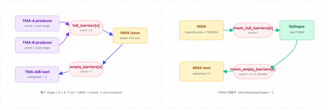
Input Buffer Pool
[1] input_token_buffer
- Shape:
[num_tokens, hidden] - Dtype: FP8 E4M3
- Purpose: Activation input for tokens
- Write: Written by the Host,
buffer.x[:num_tokens].copy_(x_fp8) - Read: During the dispatch pull phase, accessed across ranks via
sym_buffer.map().ptx::tma_load_1d(pull_buffer, sym_buffer.map(input_token_buffer.get_data_buffer(src_token_idx).get_base_ptr(), dst_rank_idx), pull_mbarrier, kHidden);
[2] input_sf_buffer
- Shape:
[num_tokens, hidden/128] - Dtype: UE8M0
- Purpose: Scale Factor for input tokens (K-major)
- Write: Written by the Host,
buffer.x_sf[:num_tokens].copy_(x_sf) - Read: During the dispatch pull phase, using regular LD/ST (non-TMA).
const auto remote_sf_ptr = sym_buffer.map(input_sf_buffer.get_data_buffer(src_token_idx).get_base_ptr<uint32_t>(), current_rank_in_expert_idx); - ⚠️ Note: This SF uses a K-major layout (arranged along the hidden dimension), while
l1_sf_bufferandl2_sf_bufferare M-major. The conversion is completed when writing tol1_sf_bufferduring the dispatch pull viatransform_sf_token_idx.
[3] input_topk_idx_buffer
- Shape:
[num_tokens, num_topk] - Dtype: int64
- Purpose: Expert routing indices, used to determine which expert each token is routed to. A value of -1 indicates the slot is unused (masked).
- Write: Written by the Host,
buffer.x_sf[:num_tokens].copy_(x_sf) - Read: During the dispatch warp phase, read via
__ldg().__ldg(input_topk_idx_buffer.get_base_ptr<int64_t>() + i * kNumTopk + lane_idx)
[4] input_topk_weights_buffer
- Shape:
[num_tokens, num_topk] - Dtype: float32
- Purpose: Top-k weights
- Write: Written by the Host,
buffer.topk_weights[:num_tokens].copy_(topk_weights) - Read: During the dispatch pull phase, pulled locally together with the token and stored in [7]
l1_topk_weights_buffer.sym_buffer.map(input_topk_weights_buffer.get_base_ptr<float>() + src_token_topk_idx, dst_rank_idx)
[1] input_token_buffer
Shape: [num_tokens, hidden] Dtype: FP8 E4M3
Purpose: Input token activations
Write: Written by Host, buffer.x[:num_tokens].copy_(x_fp8)
Read: During the dispatch pull phase, accessed across ranks via sym_buffer.map()
ptx::tma_load_1d(pull_buffer, sym_buffer.map(input_token_buffer.get_data_buffer(src_token_idx).get_base_ptr(), dst_rank_idx), pull_mbarrier, kHidden);
[2] input_sf_buffer
Shape: [num_tokens, hidden/128] Dtype: UE8M0
Purpose: Scale Factor for input tokens (K-major)
Write: Written by Host, buffer.x_sf[:num_tokens].copy_(x_sf)
Read: During the dispatch pull phase, regular LD/ST (non-TMA)
const auto remote_sf_ptr = sym_buffer.map(input_sf_buffer.get_data_buffer(src_token_idx).get_base_ptr<uint32_t>(), current_rank_in_expert_idx);
⚠️ Note: This SF uses K-major layout (arranged along the hidden dimension), while l1_sf_buffer and l2_sf_buffer use M-major layout. The conversion is performed via transform_sf_token_idx when writing to l1_sf_buffer during dispatch pull.
[3] input_topk_idx_buffer
Shape: [num_tokens, num_topk] Dtype: int64
Purpose: Expert routing indices, used to determine which experts each token is routed to. A value of -1 indicates the slot is unused (masked).
Write: Written by Host, buffer.x_sf[:num_tokens].copy_(x_sf)
Read: During the dispatch warp phase, read via __ldg()
__ldg(input_topk_idx_buffer.get_base_ptr<int64_t>() + i * kNumTopk + lane_idx)
[4] input_topk_weights_buffer
Shape: [num_tokens, num_topk] Dtype: float32
Purpose: Top-k weights
Write: Written by Host, buffer.topk_weights[:num_tokens].copy_(topk_weights)
Read: During the dispatch pull phase, pulled locally together with tokens and stored into [7] l1_topk_weights_buffer
sym_buffer.map(input_topk_weights_buffer.get_base_ptr<float>() + src_token_topk_idx, dst_rank_idx)
[1] input_token_buffer
Shape: [num_tokens, hidden] Dtype: FP8 E4M3
- Purpose: Input token activations
- Write: Written by Host,
buffer.x[:num_tokens].copy_(x_fp8) - Read: During the dispatch pull phase, accessed across ranks via
sym_buffer.map()
Purpose: Input token activations
Write: Written by Host, buffer.x[:num_tokens].copy_(x_fp8)
Read: During the dispatch pull phase, accessed across ranks via sym_buffer.map()
ptx::tma_load_1d(pull_buffer, sym_buffer.map( input_token_buffer.get_data_buffer(src_token_idx).get_base_ptr(), dst_rank_idx), pull_mbarrier, kHidden);
[2] input_sf_buffer
Shape: [num_tokens, hidden/128] Dtype: UE8M0
- Purpose: Scale Factor for input tokens (K-major)
- Write: Written by Host,
buffer.x_sf[:num_tokens].copy_(x_sf) - Read: During the dispatch pull phase, regular LD/ST (non-TMA)
Purpose: Scale Factor for input tokens (K-major)
Write: Written by Host, buffer.x_sf[:num_tokens].copy_(x_sf)
Read: During the dispatch pull phase, regular LD/ST (non-TMA)
const auto remote_sf_ptr = sym_buffer.map( input_sf_buffer.get_data_buffer(src_token_idx).get_base_ptr<uint32_t>(), current_rank_in_expert_idx);
⚠️ Note: This SF uses K-major layout (arranged along the hidden dimension), while l1_sf_buffer and l2_sf_buffer use M-major layout. The conversion is performed via transform_sf_token_idx when writing to l1_sf_buffer during dispatch pull.
[3] input_topk_idx_buffer
Shape: [num_tokens, num_topk] Dtype: int64
- Purpose: Expert routing indices, used to determine which experts each token is routed to. A value of -1 indicates the slot is unused (masked).
- Write: Written by Host,
buffer.x_sf[:num_tokens].copy_(x_sf) - Read: During the dispatch warp phase, read via
__ldg()
Purpose: Expert routing indices, used to determine which experts each token is routed to. A value of -1 indicates the slot is unused (masked).
Write: Written by Host, buffer.x_sf[:num_tokens].copy_(x_sf)
Read: During the dispatch warp phase, read via __ldg()
__ldg(input_topk_idx_buffer.get_base_ptr<int64_t>() + i * kNumTopk + lane_idx)
[4] input_topk_weights_buffer
Shape: [num_tokens, num_topk] Dtype: float32
- Purpose: Top-k weights
- Write: Written by Host,
buffer.topk_weights[:num_tokens].copy_(topk_weights) - Read: During the dispatch pull phase, pulled locally together with tokens and stored into [7]
l1_topk_weights_buffer
Purpose: Top-k weights
Write: Written by Host, buffer.topk_weights[:num_tokens].copy_(topk_weights)
Read: During the dispatch pull phase, pulled locally together with tokens and stored into [7] l1_topk_weights_buffer
sym_buffer.map( input_topk_weights_buffer.get_base_ptr<float>() + src_token_topk_idx, dst_rank_idx)
L1 Pool (Linear1 Input/Output Buffer)
[5] l1_token_buffer
Shape:[max_pool_tokens][kHidden]Dtype:FP8
Purpose: Stores all tokens dispatched to this rank. This is the largest segment in the entire buffer.
Write: dispatch pull warp, executed via TMA:
ptx::tma_store_1d( l1_token_buffer.get_data_buffer(pool_token_idx).get_base_ptr(), pull_buffer.get_base_ptr(), pull_buffer.get_num_bytes());
Read: TMA-Producer A warp (via TMA descriptor → tensor_map_l1_acts):
tma::copy<BLOCK_K, LOAD_BLOCK_M, swizzle>( &tensor_map_l1_acts, full_barriers[stage], smem_a[stage], k_idx, m_idx, 2);
Data flow: dispatch pull → l1_token_buffer → GEMM TMA-Producer A load → MMA
[6] l1_sf_buffer
Shape:[max_pool_tokens][kHidden/128]Dtype:UE8M0
Purpose: L1 Pool Scale Factor (M-major)
Write: dispatch pull warp (regular LD/ST):
local_sf_ptr[j * kNumPaddedSFPoolTokens + sf_pool_token_idx] = remote_sf_ptr[j];
// Then perform UTCCP 4×32 transpose address mapping via transform_sf_token_idx
Read: TMA-Producer A warp (via TMA descriptor → tensor_map_l1_acts_sf):
tma::copy<SF_BLOCK_M,1,0>(&tensor_map_l1_acts_sf, full_barriers[stage], smem_sfa[stage], sfa_m_idx, sfa_k_idx, 2);
// After loading, copy to the SFA column of TMEM via UTCCP
[7] l1_topk_weights_buffer
Shape:[max_pool_tokens]Dtype:float
Purpose: Top-k Weight for Pool Tokens
Write: dispatch pull warp:
*l1_topk_weights_buffer.get_data_buffer(pool_token_idx).get_base_ptr<float>() = weight;
Read: L1 epilogue warp (SwiGLU phase). When the L1 epilogue performs the SwiGLU activation, it must multiply by each token's top-k weight:
silu(gate) × up × weight.
stored_cached_weight = *l1_topk_weights_buffer.get_data_buffer(m_idx + ...).get_base_ptr<float>();
L2 Pool (Linear2 Input/Output Buffer, Reusing L1 Output)
[8] l2_token_buffer
Shape:[max_pool_tokens][L1_OUT_BLOCK_N]Dtype:BF16
Purpose: L2 Pool Token (FP8 Intermediate), where l2_token_buffer and l1_token_buffer use the same physical tensor (l2_acts view), but with different shapes and strides.
Write: L1 epilogue (TMA store)
SM90_TMA_STORE_2D::copy(&tensor_map_l1_output, smem_cd, out_n_idx, m_idx);// tensor_map_l1_output points to l2_acts (i.e., l2_token_buffer), N dimension = intermediate_hidden// but swizzle mode is halved (64 vs 128), because post-SwiGLU N is BLOCK_N/2
Read: TMA-Producer-A warp (L2 phase)
tma::copy<BLOCK_K, LOAD_BLOCK_M, swizzle>( &tensor_map_l2_acts, full_barriers[stage], smem_a[stage], k_idx, m_idx, 2);
Data flow: L1 MMA → L1 epilogue → TMA store → l2_token_buffer → L2 TMA-A load → L2 MMA
[9] l2_sf_buffer
Shape:[max_pool_tokens][L2_SHAPE_K/32]Dtype:UE8M0
Purpose: L2 Pool Scale Factor (M-major)
Write: L1 epilogue warp (after SwiGLU quantization)
sf_base_ptr[sf_addr] = (*reinterpret_cast<const uint32_t*>(&sf.x) >> 23); → Convert float SF to UE8M0 format, write to M-major layout
Read: TMA-A warp (L2 phase)
tma::copy<SF_BLOCK_M, 1, 0>( &tensor_map_l2_acts_sf, full_barriers[stage], smem_sfa[stage], sfa_m_idx, sfa_k_idx, 2);
Combine Buffer
combine_token_buffer
Shape: [kNumTopk][num_tokens][kHidden]
Dtype: BF16
- Write: L2 epilogue warp (BF16 write-back via NVLink)
// Obtain (dst_rank, dst_token, dst_topk)
src_metadata = get_token_src_metadata_ptr(pool_token_idx);
const auto dst_token = combine_token_buffer.get_rank_buffer(dst_topk_idx)  // Select rank sub-region by topk slot
    .get_data_buffer(dst_token_idx);  // Locate by token index
*sym_buffer.map(dst_ptr, dst_rank_idx) = packed;  // Cross-rank NVLink write
- Read: Combine phase (local read on this rank), TMA load BF16 tokens from each topk slot → float accumulation → TMA store to y
combine_token_buffer.get_rank_buffer(slot_idx).get_data_buffer(token_idx).get_base_ptr();
Data interaction flow:
L2 MMA → L2 epilogue → NVLink write → combine_token_buffer (buffer on remote rank)
NVLink write (L2 epilogue on remote rank) → combine_token_buffer on this rank → Combine warp TMA load → float reduce → TMA store → output y
4. Detailed Code Analysis
Next, we perform a detailed analysis of the five warps in the computation.
sm100_fp8_fp4_mega_moe_impl is a persistent fused kernel that sequentially completes, within a single grid launch: Dispatch → Linear1 GEMM (+SwiGLU) → Linear2 GEMM → Combine. The warps in the entire grid are divided into 5 roles based on warp_idx. One detail is that MegaMoE allocates different registers for different warps.
Why does the epilogue use 208 registers?
- SwiGLU needs to process 2 gate/up pairs simultaneously (8 floats)
- Amax reduction requires caching
- The topk accumulation in the Combine phase requires a large number of temporary registers
- Register spilling is extremely costly; it is better to allocate more registers
The function of each warp has been detailed in Section 3.1. Here, we expand from the code level and analyze some of the details.
4.1 Dispatch Warp
4.1.1 Counting the Number of Tokens Sent to Expert i on This SM
The original input consists of N tokens, each with its own topk_idx. The Dispatch Warp needs to process them in parallel and count how many tokens each expert has. A function is used here:
// Lines 366–383
const auto read_topk_idx = [&](const auto& process) {
    #pragma unroll
    for (uint32_t i = (sm_idx * kNumDispatchWarps + warp_idx) * kNumTokensPerWarp;
         i < num_tokens;
         i += kNumSMs * kNumDispatchWarps * kNumTokensPerWarp) {
        int expert_idx = -1;
        if (i + (lane_idx / kNumTopk) < num_tokens and lane_idx < kNumActivateLanes) {
            expert_idx = static_cast<int>(
                __ldg(input_topk_idx_buffer.get_base_ptr<int64_t>() + i * kNumTopk + lane_idx));
            if (expert_idx >= 0)
                process(i * kNumTopk + lane_idx, expert_idx);
        }
        __syncwarp();
    }
};
It uses the global warp id composed of (sm_idx, warp_idx) to stride through the input token sequence with a step of kNumTokensPerWarp, ensuring that all dispatch warps in the entire grid collectively and evenly cover num_tokens × kNumTopk entries. The 32 lanes within a warp are divided into kNumTokensPerWarp groups, each with kNumTopk lanes. Within a lane, the token offset is derived using lane_idx / kNumTopk, and the topk slot is derived using lane_idx % kNumTopk. It also reads the topk index from global memory using __ldg to reduce conflicts.
Then, smem_expert_count is an array of length kNumExperts in shared memory. Each thread can directly perform an atomicAdd on it.
read_topk_idx([&](const uint32_t& token_topk_idx, const int& expert_idx) { atomicAdd_block(smem_expert_count + expert_idx, 1);});ptx::sync_aligned(kNumDispatchThreads, kDispatchBarrierIdx);
[Note from Zha] There is a detail here: it uses a two-level counting method. First, it counts within the SM, which makes atomicAdd much faster than directly using global memory atomic operations. After this step is complete, it calculates the total for the entire rank in the next step. Then, the barrier here uses kDispatchBarrierIdx = 0, which is the hardware barrier index for intra-SM (bar.sync's name field). Dispatch warps within the same intra-SM share the same named barrier.
Note from Zha
There is a detail here: it uses a two-level counting method. First, it counts within the SM, which makes atomicAdd much faster than directly using global memory atomic operations. After this step is complete, it calculates the total for the entire rank in the next step.
Then, the barrier here uses kDispatchBarrierIdx = 0, which is the hardware barrier index for intra-SM (bar.sync's name field). Dispatch warps within the same intra-SM share the same named barrier.
4.1.2 Local Count → Global Offset
Use atomicAdd to write the expert send count expert_send_count[i] to the global workspace.
#pragma unroll
for (uint32_t i = thread_idx; i < kNumExperts; i += kNumDispatchThreads) {
    const uint64_t send_value =
        (1ull << 32) | static_cast<uint64_t>(smem_expert_count[i]);
    smem_expert_count[i] = static_cast<uint32_t>(
        ptx::atomic_add(workspace.get_expert_send_count_ptr(i), send_value));
}
ptx::sync_aligned(kNumDispatchThreads, kDispatchBarrierIdx);
The 64-bit value here is also a trick. The high 32 bits represent the reported SM counter, and the low 32 bits represent the cumulative token count smem_expert_count[i] for this rank on that expert from the first step. send_value = (1ull << 32) | local_count: a 64-bit addition simultaneously adds the current CTA's token count to the lower 32 bits and the "SM count" to the upper 32 bits.
ptx::atomic_add(...) returns the old value before the addition. Its lower 32 bits are the "global starting offset for this SM on that expert," which is written back to smem_expert_count[i], overwriting the original value, and serves as the base address for the next step's destination slot. Specifically, this global counter acts like a ticket dispenser. For example, if the current value is A1, after SM 1 performs atomicAdd, the counter updates to A1 + sm1_count, and the old value A1 is returned. SM 1 then knows that the interval [A1, A1 + sm0_count) is the segment for receiving data, with A1 as the starting offset on the remote expert slot. Subsequently, when SM 2 performs atomicAdd, it will return A1 + sm1_count, which serves as SM 1's starting offset on the remote expert slot.
4.1.3 Write Remote src_token_topk_idx
Based on the starting offset from the previous step, the local token's topk_idx can be written to the remote location. Why write the topk_idx to the remote side? Because the sending rank knows which token it sent to which expert, but the receiving rank, which owns the expert, is the entity that will execute the subsequent pull. It needs to be able to look up the source index for each slot directly from its local workspace, avoiding the need for a reverse NVLink lookup during the pull.
read_topk_idx([&](const uint32_t& token_topk_idx, const int& expert_idx) { const auto dst_rank_idx = expert_idx / kNumExpertsPerRank; const auto dst_slot_idx = atomicAdd_block(smem_expert_count + expert_idx, 1); const auto dst_ptr = workspace.get_src_token_topk_idx_ptr( expert_idx % kNumExpertsPerRank, sym_buffer.rank_idx, dst_slot_idx); *sym_buffer.map(dst_ptr, dst_rank_idx) = token_topk_idx;});
Here, dst_rank_idx = expert_idx / kNumExpertsPerRank: the rank where the target expert resides. dst_slot_idx = atomicAdd_block(...) means incrementing based on the SM's offset (the smem_expert_count just written back), resulting in a unique slot within the interval [SM offset, SM offset + this SM's count).
workspace.get_src_token_topk_idx_ptr(local_expert, src_rank, slot): locates the slot in the target rank's workspace. The layout is [local_expert][src_rank][slot]; where src_rank = sym_buffer.rank_idx, which is the current rank's own ID. sym_buffer.map(dst_ptr, dst_rank_idx) remaps the local workspace pointer to the corresponding address of the remote rank dst_rank_idx (the symmetric buffer assumes all ranks share the same virtual layout). The write naturally goes to the remote side via NVLink.
The written value token_topk_idx = token_idx * kNumTopk + topk_idx is the global positioning information on the source side, which the receiving side will later use to look up the token body.
At this point, this rank has told all target ranks, "These are my tokens that you need to process."
4.1.4 SM0 Aggregation
First, a grid_sync is performed. After completion, expert_send_count[i] from the second step is already the final aggregated value for this rank (all kNumSMs contributors have joined). For cross-rank writes, SM0 only needs to write once. It will update the receiving end's expert_recv_count, which is a 2D array [rank, expert_idx]. This represents the "number of tokens received from src_rank" from the receiver's perspective, used for subsequent round-robin.
Then, it also performs an atomicAdd to update the remote expert_recv_count_sum[local_expert], which is the total counter on the receiving end: the high 32 bits accumulate kNumSMs (each sending rank contributes kNumSMs), and the low 32 bits accumulate the token count. When the high 32 bits equal kNumSMs * kNumRanks, it means all SMs on all ranks have finished reporting. At this point, the low 32 bits represent the global final token count. This represents the total number of tokens sent to this expert from all ranks. In the subsequent scheduler, the fetch_expert_recv_count function will perform a ld_volatile spin loop for each expert. When all data has arrived, it triggers block dispatch scheduling and the subsequent GEMM computation.
if (sm_idx == 0) {
    #pragma unroll
    for (uint32_t i = thread_idx; i < kNumExperts; i += kNumDispatchThreads) {
        const auto dst_rank_idx = i / kNumExpertsPerRank;
        const auto dst_local_expert_idx = i % kNumExpertsPerRank;
        const auto expert_status = *workspace.get_expert_send_count_ptr(i);
        // (1) Tell the remote: how many tokens my rank sent to your local_expert
        *sym_buffer.map(
            workspace.get_expert_recv_count_ptr(sym_buffer.rank_idx, dst_local_expert_idx),
            dst_rank_idx) = expert_status & 0xffffffff;
        // (2) Aggregate into the remote sum counter: lower 32 bits = token count accumulation; upper 32 bits = completed SM count accumulation
        // atomic_add_sys(.sys scope) ensures cross-rank consistency, while ordinary atomic_add_rel only guarantees within the same device.
        ptx::atomic_add_sys(
            sym_buffer.map(workspace.get_expert_recv_count_sum_ptr(dst_local_expert_idx), dst_rank_idx),
            expert_status);
    }
}
ptx::sync_aligned(kNumDispatchThreads, kDispatchBarrierIdx);
4.1.5 NVLink Barrier
Then, an NVLink Barrier is performed to ensure that expert_recv_count[*][*] and src_token_topk_idx on all ranks have been completely written by their respective SM 0. This guarantees that when tokens are pulled later, the final values will be read.
comm::nvlink_barrier<kNumRanks, kNumSMs, kNumDispatchThreads, kDispatchGridSyncIndex, kBeforeDispatchPullBarrierTag>( workspace, sym_buffer, sm_idx, thread_idx, [=]() { ptx::sync_aligned(kNumDispatchThreads, kDispatchBarrierIdx); }, /* sync_prologue = */ false, // Already grid_synced in the previous step /* sync_epilogue = */ true // grid_sync again after completion);
There is also a barrier with the Epilogue Warp later. Its purpose is to prevent the NVLink barrier in the epilogue phase from interfering with the current pull barrier.
ptx::sync_unaligned(kNumDispatchThreads + kNumEpilogueThreads, kDispatchWithEpilogueBarrierIdx);
4.1.6 Pull Token
4.1.6.1 Initialization
Pull the token bodies (FP8 weights + scale factor + topk weights) that hit the local expert on other ranks back into the local L1 token pool, and simultaneously set l1_arrive_cnt to trigger TMA-Producer A consumption.
First, there is a context initialization process:
// Pull token data and SF from remote ranks into local L1 buffer
uint32_t pull_mbarrier_phase = 0;
// `pull_buffer`: each warp's private 1-token staging area in smem, used as the target for TMA load
const auto pull_buffer = smem_send_buffers.get_rank_buffer(warp_idx).get_data_buffer(0);
// `pull_mbarrier`: one transaction mbarrier per warp, used for TMA load completion signal
const auto pull_mbarrier = dispatch_barriers[warp_idx];
// Cache expert token counts in registers (same pattern as scheduler)
scheduler.fetch_expert_recv_count();
// Per-rank counts for current expert (re-loaded when expert changes)
// When `kNumRanks > 32`, each lane needs to manage counts for multiple ranks; otherwise `=1`;
constexpr uint32_t kNumRanksPerLane = math::constexpr_ceil_div(kNumRanks, 32u);
int current_expert_idx = -1;
// For the current expert, lane `lane_idx`'s local cache of token counts from remote rank `i*32+lane_idx`
uint32_t stored_rank_count[kNumRanksPerLane] = {};
// The `[start, end)` interval of the current expert in the global token sequence
uint32_t expert_start_idx = 0, expert_end_idx = 0;
// The starting block offset (in blocks aligned to `BLOCK_M`) of the current expert in the L1 token pool
uint32_t expert_pool_block_offset = 0;
// Total number of dispatch warps across the grid, used as the token-level sharding stride
constexpr uint32_t kNumGlobalWarps = kNumSMs * kNumDispatchWarps;
Here, scheduler.fetch_expert_recv_count() waits for the high 32 bits of expert_recv_count_sum to equal kNumSMs * kNumRanks, and caches the final token count into stored_num_tokens_per_expert[i]; each lane manages the expert with expert_idx = i*32 + lane_idx. This cache is later used by fetch_next_l1_block and get_pool_block_offset.
4.1.6.2 Main Loop
Next, the main loop begins, processing tokens in a token-level sharded manner. Each dispatch warp iterates over the merged token sequence of this rank (all local experts concatenated end-to-end) with a stride of kNumGlobalWarps and a starting point of global_warp_id, advancing the expert pointer internally.
for (uint32_t token_idx = sm_idx * kNumDispatchWarps + warp_idx; ; token_idx += kNumGlobalWarps) {
    int old_expert_idx = current_expert_idx;
    while (token_idx >= expert_end_idx) {
        if (++ current_expert_idx >= kNumExpertsPerRank)
            break;
        // Update pool block offset for the new expert
        expert_pool_block_offset += math::ceil_div(expert_end_idx - expert_start_idx, BLOCK_M);
        // Move start and end to the next expert
        expert_start_idx = expert_end_idx;
        expert_end_idx += scheduler.get_num_tokens(current_expert_idx);
    }
     // Finish all tokens
    if (current_expert_idx >= kNumExpertsPerRank) break;

    // Subsequent processing...
}
The entire token_idx increases monotonically. The while loop continues scanning forward from the previous expert; when switching experts, expert_pool_block_offset is incremented cumulatively. We use a simple example with BLOCK_M = 8 to illustrate the token layout as follows:
In the table above, this is a monotonic progression: token_idx increases sequentially, so each while loop only needs to scan forward from the previous expert. When switching experts, the number of m-blocks occupied by the previous expert is calculated using (end - start), accumulated into expert_pool_block_offset, and then (start, end) is rolled to the next expert's interval.
Next, when switching experts, per-rank counter reloading is triggered. The lane fetches the counters for the ranks it manages from workspace.get_expert_recv_count_ptr(j, cur), updating the per-rank counter expert_recv_count[src_rank][local_expert]. For example, when processing the 10 tokens of Expert 0, as shown in the figure above, these 10 tokens may come from different ranks. The following code reads the corresponding rank's value into the register stored_rank_count[i] for each lane, providing data for the subsequent min-peeling process.
if (old_expert_idx != current_expert_idx) { old_expert_idx = current_expert_idx; #pragma unroll for (uint32_t i = 0; i < kNumRanksPerLane; ++ i) { const uint32_t j = i * 32 + lane_idx; stored_rank_count[i] = j < kNumRanks ? static_cast<uint32_t>(*workspace.get_expert_recv_count_ptr(j, current_expert_idx)) : 0; }}
4.1.6.3 Min-Peeling Algorithm
This part essentially determines the order in which tokens of a given expert are pulled to the local node via NVLink, while striving for load balance throughout the pull process. The previous step obtained the counter stored_rank_count[i] indicating which ranks the tokens within a single expert come from. Then, this step uses a round-robin approach to map tokens from different ranks to the corresponding slots of this expert. The specific calculation flow is illustrated in the following example:
The stored_rank_count generated in the previous step serves as the initial value for each token iteration, copied to the working copy remaining[]. Then, a min-peeling method is used to round-robin among ranks to select the source of the current token. For example, in the first round, ranks with non-zero remaining[] are identified as active_rank. Initially, all ranks are active, so num_active_ranks = 4. Then, the minimum length among all active ranks is found: minlength = 1 (Rank3 has the smallest length). The number of tokens to be pulled in this round is calculated as num_active_ranks x min_length, and the pull is performed. The same algorithm is then iterated until completion. Below, we examine the detailed code implementation.
The initialization phase is as follows: it copies stored_rank_count into remaining[] and converts the currently processed token_idx into the relative coordinate slot_idx within the current expert.
uint32_t remaining[kNumRanksPerLane];for (uint32_t i = 0; i < kNumRanksPerLane; ++i) remaining[i] = stored_rank_count[i]; // create a copyuint32_t offset = 0;uint32_t token_idx_in_expert = token_idx - expert_start_idx; // relative position within this expertuint32_t slot_idx = token_idx_in_expert; uint32_t token_idx_in_rank;
Then, a loop begins. Inside the loop, it first finds the minimum length among the remaining values of all active ranks and counts active_ranks. Since each lane processes kNumRanksPerLane in parallel, it first performs statistics within the lane, then uses warp-level reductions __reduce_min_sync / __reduce_add_sync for computation.
// First aggregate the count and minimum of active ranks within a lane, then warp reduce
        uint32_t num_actives_in_lane = 0;
        uint32_t min_in_lane = 0xffffffff;
#pragma unroll
        for (uint32_t i = 0; i < kNumRanksPerLane; ++i) {
          num_actives_in_lane += remaining[i] > 0;
          if (remaining[i] > 0)
            min_in_lane = cute::min(min_in_lane, remaining[i]);
        }

        //warp reduce
        const uint32_t num_active_ranks =
            __reduce_add_sync(0xffffffff, num_actives_in_lane);
        const uint32_t length = __reduce_min_sync(0xffffffff, min_in_lane);

        // Number of tokens in this round = length × num_active_ranks
        const uint32_t num_round_tokens = length * num_active_ranks;
Then, based on num_round_tokens, it processes the hit tokens, i.e., slot_idx < num_round_tokens. The data to be processed actually forms a two-dimensional grid of [length][num_active_ranks], as shown below:
In the figure, num_active_ranks = 4, length = 2. This forms a 2D structure with length rows and active_ranks columns, where slot_idx is sorted in row-major order.
if (slot_idx < num_round_tokens) {  // Hit in this round
          const uint32_t slot_idx_in_round = slot_idx % num_active_ranks; // Which slot within this round
          uint32_t num_seen_ranks = 0;
          current_rank_in_expert_idx = 0;
#pragma unroll
          for (uint32_t i = 0; i < kNumRanksPerLane; ++i) {
            const uint32_t mask = __ballot_sync(0xffffffff, remaining[i] > 0);
            const uint32_t num_active_lanes = __popc(mask);
            if (slot_idx_in_round >= num_seen_ranks and
                slot_idx_in_round < num_seen_ranks + num_active_lanes)
              current_rank_in_expert_idx =
                  i * 32 +
                  __fns(mask, 0, slot_idx_in_round - num_seen_ranks + 1);
            num_seen_ranks += num_active_lanes;
          }
          token_idx_in_rank = offset + (slot_idx / num_active_ranks);
          break;
        }
The ballot + fns approach here uses a common CUDA parallel computing technique involving __ballot_sync and __fns. These are warp-level primitives used for efficient inter-thread communication and bit manipulation. __ballot_sync(unsigned mask, int predicate) is a "voting" primitive. Within a warp, it evaluates a condition; if predicate is true (non-zero), the corresponding thread sets the corresponding bit in the resulting integer. It generates a 32-bit mask, with the highest bit corresponding to the voting result of 32 threads. In the code, remaining[i] > 0 is used as the predicate for voting, and the resulting mask indicates which ranks are active. Then, __popc(mask) gives the number of active ranks. __fns(unsigned mask, unsigned base, k) — fns stands for "find-n-th-set" — finds the position of the n-th set bit in a 32-bit integer. Using this function, it finds the position of the (slot - num_seen) + 1-th set bit, obtaining the rank offset within the group, and then adds i*32 to get the global rank number.
ballot + fns
This approach uses a common CUDA parallel computing technique involving __ballot_sync and __fns. These are warp-level primitives used for efficient inter-thread communication and bit manipulation.
__ballot_sync(unsigned mask, int predicate) is a "voting" primitive. It performs a conditional test within a warp; if predicate is true (non-zero), the corresponding thread sets the corresponding bit in the resulting integer. It maps to generating a 32-bit mask, where the highest bit corresponds to the voting result of the 32 threads. In the code, remaining[i] > 0 is used as the predicate for voting, and the resulting mask indicates which ranks are active. Then, __popc(mask) gives the number of active ranks.
__fns(unsigned mask, unsigned base, k) — fns stands for "find-n-th-set". This function finds the position of the n-th set bit in a 32-bit integer. Using this method, it finds the bit position of the (slot - num_seen) + 1-th set bit, obtains the rank offset within the group, and then adds i*32 to get the global rank number.
After completing this round, it updates by subtracting the slots consumed in this round, accumulates the offset within the rank, and subtracts length from all ranks to prepare for the next round.
slot_idx -= num_round_tokens;
offset += length;

#pragma unroll
for (uint32_t i = 0; i < kNumRanksPerLane; ++i) {
    remaining[i] -= cute::min(remaining[i], length);
}
Looking at the overall algorithm implementation, the 32 lanes within a warp fully cooperate to complete a single query. The processing complexity is O(kNumRanks) (in the worst case, it needs to peel kNumRanks-1 times), but typically the number of peels is far less than the number of ranks. Finally, it achieves load balancing very simply: even if one rank sends a large number of tokens while others send fewer, they will be interleaved in a round-robin fashion. This is critical for subsequent NVLink bandwidth utilization, as at any given time, all dispatch warps are more likely to target different remote ranks, avoiding a single-rank communication bottleneck.
4.1.6.5 Pull token
This step pulls the token payload (FP8 weights + scale factor + topk weights) from other ranks that hit the local expert into the local L1 token pool, and simultaneously sets l1_arrive_cnt to trigger TMA-Producer A consumption.
First, it reads src_token_topk_idx:
// Read source token-topk index (written by remote dispatch via NVLink)
const uint32_t src_token_topk_idx = *workspace.get_src_token_topk_idx_ptr(
    current_expert_idx,
    current_rank_in_expert_idx,
    token_idx_in_rank);
const uint32_t src_token_idx = src_token_topk_idx / kNumTopk;
const uint32_t src_topk_idx = src_token_topk_idx % kNumTopk;
get_src_token_topk_idx_ptr uses a three-dimensional index: expert_idx (local expert), rank_idx (source rank), token_idx (token sequence number within that rank and expert). It points to a uint32_t storing token_topk_idx, which is the position of this token in the source rank's global topk index array. The value is token_topk_idx = src_token_idx * kNumTopk + src_topk_idx, written by the remote rank during the dispatch push phase:
src_token_idx: The row number in the inputXof the remote rank.src_topk_idx: The topk slot occupied by this token when it selected this expert (used later during combine to fill back into the correct topk row).
The parameters for this function call are:
| Index | Meaning |
|---|---|
current_expert_idx | The local expert index on this rank (0 ~ kNumExpertsPerRank-1) |
current_rank_in_expert_idx | The "remote rank index" from which this expert's tokens originate in the current round, selected by min-peeling round-robin |
token_idx_in_rank | The sequence number (offset within the rank) of the token received by this expert from this remote rank |
TMA Token Pull
Then, these two values are decoded for TMA. The destination address is smem_send_buffers, which is the dispatch area's shared memory, with a layout of [kNumDispatchWarps][1 token][fp8_token_layout], one row per warp. get_data_buffer(0) takes the starting point of this warp's row, with a length exactly equal to kHidden bytes (the FP8 data of one token row).
The source tensor input_token_buffer is a row-major FP8 tensor of [num_max_tokens_per_rank][kHidden]. It is addressed via src_token_idx.
const auto pull_buffer = smem_send_buffers.get_rank_buffer(warp_idx).get_data_buffer(0);

// TMA load token from remote rank into shared memory
if (cute::elect_one_sync()) {
    ptx::tma_load_1d(
        pull_buffer.get_base_ptr(),  // dst
        sym_buffer.map(
            input_token_buffer.get_data_buffer(src_token_idx).get_base_ptr(),
            current_rank_in_expert_idx),  // src
        pull_mbarrier,
        kHidden);
}
__syncwarp();
Direct LD of ScalingFactor
The total byte count of SF is kHidden / 32 = kNumSFUint32 × 4, which is very small. It is directly copied using warp-parallel LDG/STG. This runs in parallel with the TMA token load: while the token is still traversing the TMA pipeline, the 32 lanes have already moved the SF from the remote rank to the local l1_sf_buffer.
constexpr uint32_t kNumSFUint32 = kHidden / 128;
DG_STATIC_ASSERT(kNumSFUint32 > 0 and kHidden % 128 == 0, "Invalid SF");

const auto remote_sf_ptr = sym_buffer.map(
    input_sf_buffer.get_data_buffer(src_token_idx).get_base_ptr<uint32_t>(),
    current_rank_in_expert_idx);
const auto local_sf_ptr = l1_sf_buffer.get_base_ptr<uint32_t>();
const auto sf_pool_token_idx =
    expert_pool_block_offset * SF_BLOCK_M + transform_sf_token_idx(token_idx_in_expert);

#pragma unroll
for (uint32_t i = 0; i < math::constexpr_ceil_div(kNumSFUint32, 32u); ++i) {
    const uint32_t j = i * 32 + lane_idx;
    if (j < kNumSFUint32) {
        local_sf_ptr[j * kNumPaddedSFPoolTokens + sf_pool_token_idx] = remote_sf_ptr[j];
    }
}
__syncwarp();
UTCCP 4×32 Transpose
Note that transform_sf_token_idx is called here. The SF in the pool is not laid out flat by token; instead, it is rearranged for the memory layout required by the SM100 UTCCP instruction. The destination address is local_sf_ptr[j * kNumPaddedSFPoolTokens + sf_pool_token_idx]: SF is stored in a [sf_channel, pool_token] layout (to facilitate subsequent GEMM warps loading by BLOCK_M × SF_CHTile).
topk_weight Copy
Next, it also pulls the corresponding topk_weight:
const auto weight = *sym_buffer.map(
    input_topk_weights_buffer.get_base_ptr<float>() + src_token_topk_idx,
    current_rank_in_expert_idx);
*l1_topk_weights_buffer.get_data_buffer(pool_token_idx).get_base_ptr<float>() = weight;
4.1.6.5 Pull Post-Processing
In the post-processing phase, it waits for the TMA pull to complete, then uses TMA to store the pulled token data into the local l1_token_buffer. It also writes the token metadata.
// Wait for TMA load to complete
    ptx::mbarrier_arrive_and_set_tx(pull_mbarrier, kHidden);
    ptx::mbarrier_wait_and_flip_phase(pull_mbarrier, pull_mbarrier_phase);
    // TMA store to local l1_token_buffer
    ptx::tma_store_1d(
        l1_token_buffer.get_data_buffer(pool_token_idx).get_base_ptr(),
        pull_buffer.get_base_ptr(), pull_buffer.get_num_bytes());
    // Write source metadata for combine stage to send results back to source rank
    *workspace.get_token_src_metadata_ptr(pool_token_idx) =
        {current_rank_in_expert_idx, src_token_idx, src_topk_idx};
    // Wait for TMA store to complete
    cute::tma_store_arrive();
    ptx::tma_store_wait<0>();
Finally, the most critical step is updating l1_arrive_count to notify the GEMM TMA-Producer A whether the data pull is complete, enabling the subsequent GEMM computation pipeline.
ptx::red_add_rel( workspace.get_l1_arrival_count_ptr(expert_pool_block_offset + token_idx_in_expert / BLOCK_M), 1);
4.2 TMA Producer A Warp
In the GEMM phase of the MegaMoE kernel, this warp acts as the "producer that loads activations and their scale factors". It is driven by the scheduler via scheduler.for_each_block.
4.2.1 Scheduler
The entire code is driven by the scheduler scheduler.for_each_block. The same scheduler drives four warps — TMA-A, TMA-B, MMA, and Epilogue — sharing the iteration space. The code is as follows:
template <typename Func>
CUTLASS_DEVICE void for_each_block(Func&& func) {
    // Wait for all expert counters to finish aggregation
    fetch_expert_recv_count();
    // Start traversal from expert 0 (also initialize current_num_tokens and pool offset)
    set_expert_idx(0);
    // Traverse all blocks assigned to the current SM
    while (true) {
      // Unpack the returned tuple into local variables with the same names (CUTE_TIE_DECL is a structured binding macro)
      CUTE_TIE_DECL(get_next_block(), block_phase, current_local_expert_idx,
                    m_block_idx, n_block_idx);
      if (block_phase == BlockPhase::None) break;
      // Callback signature: (BlockPhase, expert_idx, num_k_blocks, m_block_idx,
      // n_block_idx)
      func(block_phase, current_local_expert_idx,
           block_phase == BlockPhase::Linear2 ? kNumL2BlockKs : kNumL1BlockKs,
           m_block_idx, n_block_idx);
    }
  }
};
fetch_expert_recv_count() spins waiting for the aggregated recv count of each expert in the workspace to be ready. It checks whether the high 32 bits of the counter have reached kNumSMs * kNumRanks. Once it confirms that all SMs across all ranks have completed Dispatch counting, it writes the low 32 bits (the token count) into the register array stored_num_tokens_per_expert[i]. This step is the global synchronization point between dispatch and compute: only after the token counts for all experts are determined can the M-dimension block partitioning begin.
It then resets the expert index to the 0th local expert and begins traversal. Inside a while(true) loop, it repeatedly calls get_next_block(), which returns a tuple (phase, expert, m_block, n_block). The scheduling order is as follows:
Linear1 hit → return L1 block; block_idx += kNumSMs scroll to next global block
Linear1 exhausted → next_phase = Linear2, expert rewinds to current wave start
Linear2 hit → return L2 block
Linear2 exhausted → next_phase = Linear1, proceed to next wave
All done → return BlockPhase::None, break out of loop
TMA-Producer A is responsible for only one thing: pulling activation A + SFA into the A pipeline stage in shared memory via TMA. It uses for_each_block to repeat this operation for every block, so the entire execution logic is encapsulated within this function.
scheduler.for_each_block([&](const sched::BlockPhase& block_phase,
                             const uint32_t& local_expert_idx,
                             const uint32_t& num_k_blocks,
                             const uint32_t& m_block_idx, const uint32_t& n_block_idx) {
    /* ... TMA Load A processing ... */
});
The callback parameters of this function are explained as follows:
The entire warp advances internally based solely on (expert, phase, m_block, n_block) within the scheduler.
4.2.2 Tensor_map Handling
The TMA descriptor is already initialized during kernel launch. Since the two GEMM data sources for Expert FFN are completely different: 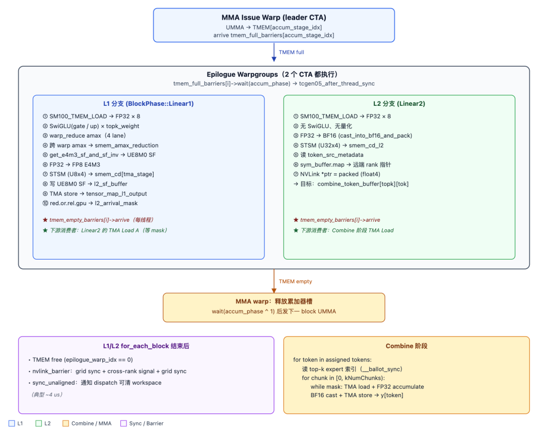
It decides whether to use the L1 or L2 tensor_map based on the returned Phase.
const auto tensor_map_a_ptr = block_phase == sched::BlockPhase::Linear2 ? &tensor_map_l2_acts : &tensor_map_l1_acts;const auto tensor_map_sfa_ptr = block_phase == sched::BlockPhase::Linear2 ? &tensor_map_l2_acts_sf : &tensor_map_l1_acts_sf;
It then computes pool_block_idx. scheduler.get_current_pool_block_offset() returns the starting block offset of the current expert in the pool. Adding m_block_idx yields the global block number of the m_block_idx-th M-dimension tile of this expert in the shared pool.
// Compute pool block offset for this expertconst uint32_t pool_block_idx = scheduler.get_current_pool_block_offset() + m_block_idx;
4.2.3 Waiting for Data Arrival Mechanism
The L1 phase waits by checking the l1_arrive_cnt updated by the Dispatch warp. The L2 phase waits by checking the l2_arrive_mask updated by the L1 Epilogue warp.
if (block_phase == sched::BlockPhase::Linear1) {
    // L1: Wait until all tokens of this m block have arrived (l1_arrival_count == valid_m)
    const auto ptr = workspace.get_l1_arrival_count_ptr(pool_block_idx);
    const auto expected = scheduler.template get_valid_m<false>();
    while (ptx::ld_acq(ptr) != expected);
} else {
    // L2: Wait until the lower 2 * num_k_blocks bits of l2_arrival_mask are all 1
    DG_STATIC_ASSERT(BLOCK_K == BLOCK_N, "Invalid block sizes");
    const auto ptr = workspace.get_l2_arrival_mask_ptr(pool_block_idx);
    const uint64_t expected = ((1ull << num_k_blocks) << num_k_blocks) - 1;
    while (ptx::ld_acq_gpu(ptr) != expected);
}
Why shift twice? When num_k_blocks == 32, uint64_t expected = (1ull << (2 * num_k_blocks)) - 1; causes 1ull << 64 → UNDEFINED BEHAVIOR. Shifting twice, each time ≤ 32, keeps both shifts within the valid [0, 63] range. uint64_t expected = ((1ull << num_k_blocks) << num_k_blocks) - 1; // num_k_blocks == 32: // (1ull << 32) = 0x100000000 // << 32 = 0 (high bits overflow) // - 1 = 0xFFFFFFFFFFFFFFFF
Why shift twice? When num_k_blocks == 32, uint64_t expected = (1ull << (2 * num_k_blocks)) - 1; causes 1ull << 64 → UNDEFINED BEHAVIOR. Shifting twice, each time ≤ 32, keeps both shifts within the valid [0, 63] range. uint64_t expected = ((1ull << num_k_blocks) << num_k_blocks) - 1; // num_k_blocks == 32: // (1ull << 32) = 0x100000000 // << 32 = 0 (high bits overflow) // - 1 = 0xFFFFFFFFFFFFFFFF
Why shift twice
When num_k_blocks == 32, uint64_t expected = (1ull << (2 * num_k_blocks)) - 1; causes 1ull << 64 → UNDEFINED BEHAVIOR. Shifting twice, each time ≤ 32, keeps both shifts within the valid [0, 63] range.
uint64_t expected = ((1ull << num_k_blocks) << num_k_blocks) - 1;// num_k_blocks == 32:// (1ull << 32) = 0x100000000// << 32 = 0 (high bits overflow)// - 1 = 0xFFFFFFFFFFFFFFFF
4.2.3.1 L1 Waiting Mechanism
get_l1_arrival_count_ptr(pool_block_idx) points to workspace.l1_arrival_count[pool_block_idx], a uint32_t. Each time the dispatch warp successfully pulls in a token, it performs red_add_rel(count_ptr, 1), which has release semantics. Here, ptx::ld_acq has acquire semantics, pairing with it to form a release/acquire synchronization. This ensures that when the value is loaded to expected, the TMA stores by the dispatch warp to l1_token_buffer[pool_block_idx * BLOCK_M .. ] are visible to the current warp.
expected = scheduler.get_valid_m<false>() refers to the actual token count of this block. For example, as shown in the figure below, although the dispatch warp updates l1_arrive_count, blocks must be aligned to experts. This leads to padding scenarios where the actual token count of a block is less than BLOCK_M, such as block 1 and block 2 in the figure below.
For Linear1, the A tile is BLOCK_M × BLOCK_K activation; UMMA consumes the entire BLOCK_M × BLOCK_K data at once and cannot tolerate row-level uninitialized data. Therefore, the producer must wait until the entire block is filled, i.e., l1_arrive_count == expected, before initiating TMA.
4.2.3.2 L2 Waiting Mechanism
First, a detail: during L1 GEMM processing, gate and up are interleaved. After SwiGLU computation in the L1 Epilogue, the block_N size is halved, as shown in the figure below:
During L2 waiting, there is an assertion DG_STATIC_ASSERT(BLOCK_K == BLOCK_N, "Invalid block sizes");. In fact, the heuristics also fix BLOCK_K = BLOCK_N = 128. This approach ensures alignment in the K dimension during L2 GEMM. After this processing, every 2 adjacent L1 N sub-blocks (L1_OUT_BLOCK_N = BLOCK_N / 2 = 64) are concatenated into 1 L2 K sub-block (BLOCK_K = 128) of data, which is easily represented by the l2_arrive_mask bitmap.
The L2 waiting mechanism was modified between PR304 and PR316. The earliest PR304 used the following approach, waiting for 2 consecutive L1 Output data blocks via two consecutive bits (3ull) to achieve overlap between L1 and L2 computation.
// pr304if (block_phase == sched::BlockPhase::Linear2) { // The L1 output's block N is halved into `BLOCK_K / 2`, so we have to wait 2 L1 blocks' arrival DG_STATIC_ASSERT(BLOCK_K == BLOCK_N, "Invalid block sizes"); const uint64_t needed = 3ull << (k_block_idx * 2); if ((cached_l2_arrival_mask & needed) != needed) { const auto ptr = workspace.get_l2_arrival_mask_ptr(pool_block_idx); do { cached_l2_arrival_mask = ptx::ld_acq_gpu(ptr); } while ((cached_l2_arrival_mask & needed) != needed); } }
However, comments in PR316 indicate: when num_experts_per_wave is large enough to ensure L1 computation is complete by the time L2 starts, this approach actually introduces negative optimization. Therefore, it was removed in PR316. However, in the future, if num_experts_per_rank is small, causing num_experts_per_wave to be insufficiently large, it may be reintroduced. The waiting mechanism in PR316 is:
// pr316const auto ptr = workspace.get_l2_arrival_mask_ptr(pool_block_idx);// NOTES: Equivalent to `(1ull << (2 * num_k_blocks)) - 1`, but split// into two shifts to avoid undefined behavior when `num_k_blocks == 32`const uint64_t expected = ((1ull << num_k_blocks) << num_k_blocks) - 1;while (ptx::ld_acq_gpu(ptr) != expected);
4.2.4 TMA Data Loading
The pipeline main loop is as follows:
for (uint32_t k_block_idx = 0; k_block_idx < num_k_blocks; advance_pipeline(k_block_idx)) {
Here, advance_pipeline simultaneously increments k_block_idx and toggles the pipeline's stage_idx (cycling through 0..kNumStages-1) and phase (toggled when stage returns to 0). stage_idx and phase are kernel-level shared variables. The TMA Producer A warp, TMA Producer B warp, and MMA Issue warp must advance in lockstep. They all traverse blocks in exactly the same order (all via the same scheduler.for_each_block), and each block loops num_k_blocks times, so the pairing relationship strictly holds.
Synchronization between the producers (Producer A/B warp) and the consumer (MMA) is achieved through empty_barriers[i] and full_barriers[i]. Each element in these barrier arrays represents a different stage.
First, it must wait for the consumer to release.
empty_barriers[stage_idx]->wait(phase ^ 1);
empty_barriers[i] has arrival_count = 1 at initialization. When the MMA issue warp launches the UMMA for the corresponding stage (line 821), it arrives on this barrier via umma_arrive_multicast_2x1SM. phase ^ 1 indicates that each stage toggles between phase=0 and phase=1, so the wait phase must be opposite to the phase of the previous arrival.
For example, with kNumStages = 3 and num_k_blocks = 6, the stage and phase changes are as follows:
Then, the TMA coordinate calculation is:
//token pool is aligned and tightly packed by `BLOCK_M`; `m_idx` directly corresponds to the outer dimension (M axis) offset of the tensor map.
uint32_t m_idx = pool_block_idx * BLOCK_M;
//K axis advances by `BLOCK_K = 128` elements each time.
uint32_t k_idx = k_block_idx * BLOCK_K;
//SFA is aligned by `SF_BLOCK_M` in the pool, matching the UTCCP 4×32 layout
uint32_t sfa_m_idx = pool_block_idx * SF_BLOCK_M;
//Every `kGranK * 4 = 128` K elements share one SF, so the K-axis step of SFA is `k_block_idx`
uint32_t sfa_k_idx = k_block_idx;
// Add 2 CTA offsets for non-leader CTA
if (not is_leader_cta)
    m_idx += scheduler.template get_valid_m<true>() / 2;
M Offset for 2-CTA Multicast
There is a detail here: the kernel uses 2-CTA cluster GEMM, a new feature on Blackwell, as shown in the figure below:
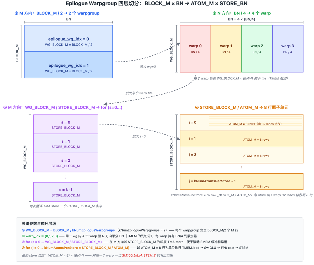
The leader CTA and non-leader CTA each load LOAD_BLOCK_M = BLOCK_M / 2 rows of activations.
Then, the TMA is issued, as shown in the code below. Here, it notifies the MMA Warp that loading is complete via full_barriers[stage_idx].
if (cute::elect_one_sync()) { tma::copy<BLOCK_K, LOAD_BLOCK_M, kSwizzleAMode, a_dtype_t>( tensor_map_a_ptr, full_barriers[stage_idx], smem_a[stage_idx], k_idx, m_idx, 2); tma::copy<SF_BLOCK_M, 1, 0>( tensor_map_sfa_ptr, full_barriers[stage_idx], smem_sfa[stage_idx], sfa_m_idx, sfa_k_idx, 2); if (is_leader_cta) { full_barriers[stage_idx]->arrive_and_expect_tx( SMEM_A_SIZE_PER_STAGE * 2 + SF_BLOCK_M * sizeof(uint32_t) * 2); } else { full_barriers[stage_idx]->arrive(0u); }
4.3 TMA Producer B Warp
The TMA Producer B warp is the GEMM weight producer for the MegaMoE kernel. It forms a symmetric dual-producer pair with the TMA Producer A warp. The differences between it and the TMA Producer A Warp are as follows:
It is also driven by the scheduler scheduler.for_each_block.
// Lines 735–738scheduler.for_each_block([&](const sched::BlockPhase& block_phase, const uint32_t& local_expert_idx, const uint32_t& num_k_blocks, const uint32_t& m_block_idx, const uint32_t& n_block_idx) { /*--- TMA Producer B Warp processing logic ---*/ }
Both TMA warps call the same scheduler's for_each_block with identical parameter signatures. Since the scheduler's internal state (stage_idx, phase, block_idx, etc.) is based on shared variables outside the lambda (uint32_t stage_idx = 0, phase = 0;), and advance_pipeline is also a shared lambda, the two warps traverse blocks in perfectly synchronized order and rhythm. Furthermore, due to branch separation, the idempotent iteration order of the scheduler, the shared stage_idx/phase, and the empty_barriers consumer synchronization, the two warps are naturally aligned on each (block, k_block) iteration.
Similarly, because the shapes of the L1/L2 weight parameters differ, TMA Producer B must use different Tensor_map for the L1 and L2 stages.
const auto tensor_map_b_ptr =
    block_phase == sched::BlockPhase::Linear2 ? &tensor_map_l2_weights : &tensor_map_l1_weights;
const auto tensor_map_sfb_ptr =
    block_phase == sched::BlockPhase::Linear2 ? &tensor_map_l2_weights_sf : &tensor_map_l1_weights_sf;
const auto shape_k = block_phase == sched::BlockPhase::Linear2 ? L2_SHAPE_K : L1_SHAPE_K;
// Added `shape_n` local variable in TMA Producer B, because B warp needs `shape_n` to compute the N offset for expert batches
const auto shape_n = block_phase == sched::BlockPhase::Linear2 ? L2_SHAPE_N : L1_SHAPE_N;
// shape_sfb_k = ceil_div(shape_k, 128)
// Indicates the number of scale rows for SFB along the K axis (every 128 K elements share one FP8 E8M0 scale)
// Used later to compute `sfb_k_idx = local_expert_idx * shape_sfb_k + k_block_idx`, locating the SFB tile for the current expert.
const auto shape_sfb_k = math::ceil_div(shape_k, kGranK * 4u);
Another difference from Producer A is that it does not need to wait and directly enters the K loop below. This is because the weights are static tensors that reside in GMEM before kernel launch, with no producer-consumer relationship.
// Directly enter K loop without any pre-waiting
for (uint32_t k_block_idx = 0; k_block_idx < num_k_blocks; advance_pipeline(k_block_idx)) {
Like Producer A Warp, it shares empty_barrier[i] and full_barrier[i] with the MMA Warp for multi-stage interaction. At the start, it waits for the consumer to release.
// Wait consumer releaseempty_barriers[stage_idx]->wait(phase ^ 1);
Both A warp and B warp wait on the same barrier. This is safe because wait is a read-only operation. Both warps will see the phase toggle simultaneously and then each refill the smem for that stage.
B/SFB TMA Coordinate Calculation
This is the most significant difference between B warp and A warp.
// Compute weight offsetuint32_t n_idx = local_expert_idx * shape_n + n_block_idx * BLOCK_N;uint32_t k_idx = k_block_idx * BLOCK_K;uint32_t sfb_n_idx = n_block_idx * BLOCK_N;uint32_t sfb_k_idx = local_expert_idx * shape_sfb_k + k_block_idx;
First, for the calculation of n_idx: local_expert_idx * shape_n jumps to the start of the weight slice for the current expert (shape_n is the total number of rows for that expert's weights in the N direction); + n_block_idx * BLOCK_N then jumps to the n_block_idx-th N tile within that expert. This is the outer dimension (N axis) offset for the TMA descriptor tensor_map_l{1,2}_weights. k_idx is exactly the same as in Producer A Warp, advancing BLOCK_K = 128 each K step.
sfb_n_idx does not include local_expert_idx * shape_n because the layout of the SFB tensor is [kNumExperts, shape_sfb_k, shape_n]. The expert batch axis is on the K side, so the N offset for SFB only contains n_block_idx * BLOCK_N, while the expert offset is calculated in the K direction. When calculating sfb_k_idx, local_expert_idx * shape_sfb_k gives the start of the SFB slice for the current expert (each row within the shape_sfb_k rows belongs to the same expert); + k_block_idx selects the k_block_idx-th SF row within that expert.
The comparison of the SF transpose issue between A and B is as follows:
The comparison between Producer A and Producer B is as follows:
Then, the TMA is issued directly, using multicast to load on both CTAs simultaneously.
// TMA copy weights with SF
if (cute::elect_one_sync()) {
    tma::copy<BLOCK_K, LOAD_BLOCK_N, kSwizzleBMode, b_dtype_t>(
        tensor_map_b_ptr,
        full_barriers[stage_idx],
        smem_b[stage_idx],
        k_idx,
        n_idx,
        2);
    tma::copy<BLOCK_N, 1, 0>(
        tensor_map_sfb_ptr,
        full_barriers[stage_idx],
        smem_sfb[stage_idx],
        sfb_n_idx,
        sfb_k_idx,
        2);
    if (is_leader_cta) {
        full_barriers[stage_idx]->arrive_and_expect_tx(
            SMEM_B_SIZE_PER_STAGE + BLOCK_N * sizeof(uint32_t) * 2);
    } else {
        full_barriers[stage_idx]->arrive(0u);
    }
}
__syncwarp();
Finally, it notifies the MMA Warp that data loading is complete via full_barriers[stage_idx].
4.4 MMA Warp
The MMA issue warp is the computational heart of the entire kernel: it consumes A/B data and SF from smem, moves the SF to TMEM via UTCCP, issues the SM1002-CTA UMMA block-scale FP8×FP4 instruction, allowing two CTAs to jointly complete the computation of one GEMM tile, with the accumulated result remaining directly in TMEM for the epilogue warp to read.
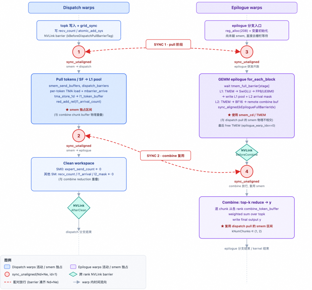
Note here that DeepSeek-V4's MoE FFN adopts a w4a8 approach, meaning the weights are FP4 and the activations are FP8. Using FP4 for weights has two benefits. First, a large number of parameters in the model are expert weights; using FP4 allows for single-node inference on an 8-GPU B-series server. Second, targeting the Memory-Bound characteristic of the Decoding phase, FP4 reduces memory bandwidth pressure and improves performance.
4.4.1 2-CTA UMMA
The semantics of the SM100 2-CTA UMMA instruction (SM100_MMA_MXF8F6F4_2x1SM_SS):
- Instruction collaboration within the cluster: The
tcgen05.mma.cta_group::2instruction is issued by the leader CTA, and the hardware automatically coordinates the data of the non-leader CTA. - Accumulator distribution: Half of the TMEM accumulation result resides in the leader CTA's TMEM, and the other half resides in the non-leader CTA's TMEM (corresponding to the upper/lower half of the M dimension).
- Single-point emission: If both CTAs emit the instruction, it will be executed twice, leading to incorrect results.
- Symmetric warp placeholder: The warp with
warp_idx == kNumDispatchWarps + 2on the non-leader CTA enters theelse ifbranch but directly skips all code afterif (is_leader_cta)— it only retains the register quota adjustment viawarpgroup_reg_dealloc, and the thread count for the same warpgroup remains 128.
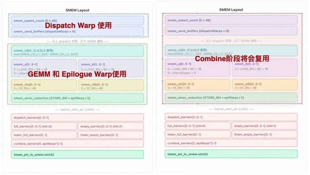
4.4.2 AB Swap
This is an optimization found in TRT-LLM PR4430 and DeepGEMM PR192, using AB Swap in the MMA, i.e., using the activation as the B matrix of the MMA and the weight as the A matrix. We note that the Blackwell (SM100) MMA instruction has a fixed M dimension of 128, which becomes 256 when 2-CTAs are combined. Consider the activation and weight in MoE:
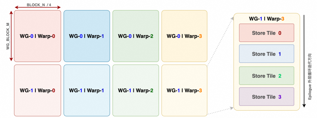
Therefore, the two operands typically used in GEMM, A (activation) and B (weight), are swapped. This AB Swap method aligns the weight with the M dimension constraint of 128/256, while the activation becomes the B operand, and then BLOCK_M alignment is constrained according to the instruction. This optimization is particularly effective for the small batch sizes in the Decoding phase, where BLOCK_M is typically small.
Another aspect is the 2-CTA design. The Blackwell 2-CTA MMA design is shown in the left diagram below. The hardware convention is: For operand A, each of the two CTAs holds half of M; for operand B, each of the two CTAs holds the full N.
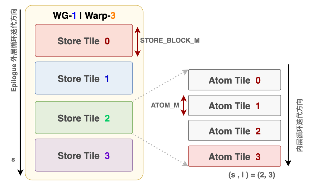
After applying AB Swap, in TMA Producer B, both CTAs load the same weight simultaneously, naturally leveraging the TMA Multicast capability:
tma::copy<BLOCK_K, LOAD_BLOCK_N, kSwizzleBMode, b_dtype_t>(
    tensor_map_b_ptr, full_barriers[stage_idx], smem_b[stage_idx],
    k_idx, n_idx, 2); // ★ num_tma_multicast = 2
tma::copy<BLOCK_N, 1, 0>(
    tensor_map_sfb_ptr, full_barriers[stage_idx], smem_sfb[stage_idx],
    sfb_n_idx, sfb_k_idx, 2); // ★ SFB also num_tma_multicast = 2
As shown in the figure below:
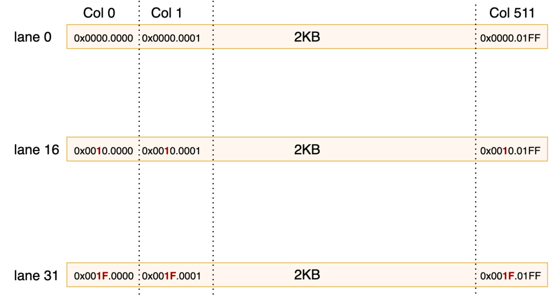
The activation, however, is computed in the M direction with each CTA handling half of the region, requiring different M rows. Therefore, it is read separately using "the same 2-CTA TMA but with different coordinates", meaning each SM reads BLOCK_M / 2.
4.4.4 MMA Config
As mentioned earlier, the activation (a_dtype_t=FP8) and weight (b_dtype_t = FP4) are defined here, along with some constraints defined in the MMA configs.
// Data types
// NOTES: activations are FP8 (e4m3), weights are FP4 (e2m1)
// Data type: activation FP8(e4m3); weight FP4(e2m1), unpacked as 8bit in smem
using a_dtype_t = cutlass::float_e4m3_t;
using b_dtype_t = cutlass::detail::float_e2m1_unpacksmem_t;

// MMA configs
// NOTES: always swap A/B, 2-CTA MMA, and matrices are K-major
// MMA configuration: fixed swap A/B here (A is weight dimension, B is activation dimension); 2-CTA UMMA; K-major
//   LAYOUT_AD_M=128       : Single CTA TMEM layout height
//   UMMA_M = 256          : Effective MMA height after 2-CTA multicast
// UMMA_N = BLOCK_M      : After swapping A/B, the N dimension equals the expert token block M
//   UMMA_K = 32           : K width of a single MMA
// LOAD_BLOCK_M = BLOCK_M/2 : After multicast on A, a single CTA only reads half
constexpr uint32_t LAYOUT_AD_M = 128;
constexpr uint32_t UMMA_M = LAYOUT_AD_M * 2;
constexpr uint32_t UMMA_N = BLOCK_M; // Swap AB
constexpr uint32_t UMMA_K = 32;
constexpr uint32_t LOAD_BLOCK_M = BLOCK_M / 2; // Multicast on A
constexpr uint32_t LOAD_BLOCK_N = BLOCK_N;

// BLOCK_M must be divisible by 16
DG_STATIC_ASSERT(BLOCK_M % 16 == 0, "Invalid block M");
// Due to AB Swap, BLOCK_N must equal LAYOUT_AD_M
DG_STATIC_ASSERT(BLOCK_N == LAYOUT_AD_M, "Invalid block N");
DG_STATIC_ASSERT(BLOCK_K == 128, "Invalid block K");
4.4.5 UMMA Instruction Construction
The instruction emission for SM100 UMMA relies on three types of descriptors:
- Instruction descriptor (shape/dtype/swizzle)
- Smem descriptor (memory layout for A, B)
- SF descriptor (for UTCCP scale factor transfer)
The instr_desc instruction descriptor is constructed as follows:
auto instr_desc = cute::UMMA::make_instr_desc_block_scaled<
    b_dtype_t, a_dtype_t, float, cutlass::float_ue8m0_t,
    UMMA_M, UMMA_N,
    cute::UMMA::Major::K, cute::UMMA::Major::K>();
Note that to implement AB Swap, the order of a_dtype_t and b_dtype_t is changed. Therefore, the template parameters expand as:
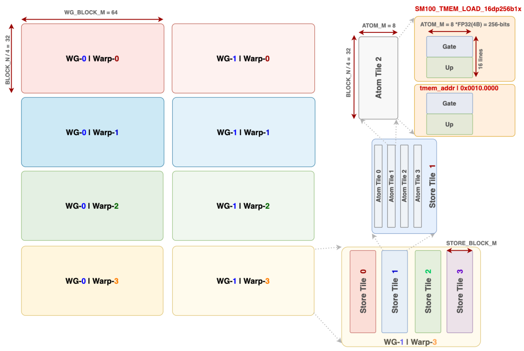
instr_desc is a cute::UMMA::InstrDescriptorBlockScaled (a variant with SF support), storing the kind/block-scaled information.
4.4.4 SF Descriptor Construction
Static fields such as flag, shape, dtype, swizzle, etc. It dynamically updates n_dim_ and a_sf_id_/b_sf_id_ within the loop. The SF descriptor sf_desc is constructed as follows:
auto sf_desc = mma::sm100::make_sf_desc(nullptr);
Referenced from mma/sm100.cuh:
cute::UMMA::SmemDescriptor make_sf_desc(void* smem_ptr) {
    // NOTES: the UTCCP layout is K-major by default
    // Atom size: 8 x 128 bits
    // {SBO, LBO} means the byte stride between atoms on {MN, K}
    // Since the UTCCP we used is 128b-wide (only 1 atom on K), so LBO can be zero
    return make_smem_desc(cute::UMMA::LayoutType::SWIZZLE_NONE, smem_ptr,
                         8 * 16, 0);
}
sf_desc is an SMEM descriptor prepared for the UTCCP (tensor memory copy) instruction. smem_ptr is passed as nullptr; the actual address is updated later via replace_smem_desc_addr before each UTCCP emission. The explanation of SBO and LBO is as follows:
- SBO (stride byte outer) =
8 * 16 = 128: The byte stride between atoms in the MN direction is 128 bytes. - LBO (stride byte inner) =
0: UTCCP moves one 128-bit atom at a time, with no stride in the K direction.
SMEM Descriptor
DG_STATIC_ASSERT(kNumStages <= 32, "Too many stages");

auto a_desc = mma::sm100::make_umma_desc<cute::UMMA::Major::K, LOAD_BLOCK_M, BLOCK_K, kSwizzleAMode>(smem_a[0], 0, 0);
auto b_desc = mma::sm100::make_umma_desc<cute::UMMA::Major::K, LOAD_BLOCK_N, BLOCK_K, kSwizzleBMode>(smem_b[0], 0, 0);
The check DG_STATIC_ASSERT(kNumStages <= 32, "Too many stages") exists because lane_idx is used as the stage index for precomputation. With 32 lanes, at most 32 stages can be covered.
make_umma_desc constructs a Cutlass UMMA SMEM descriptor, containing the start address, layout type, stride, etc. The base address is initially set to smem_a[0]/smem_b[0] (stage 0), and lane-level offsets are later used to generate versions for each stage.
Template parameters: K-major + LOAD_BLOCK_{M,N} + BLOCK_K + swizzle mode must strictly match the TMA load box parameters; otherwise, UMMA will read misaligned data.
4.4.5 Per-Lane Descriptor
An optimization follows: a_desc/b_desc are cute::UMMA::SmemDescriptor (64-bit), split into two halves:
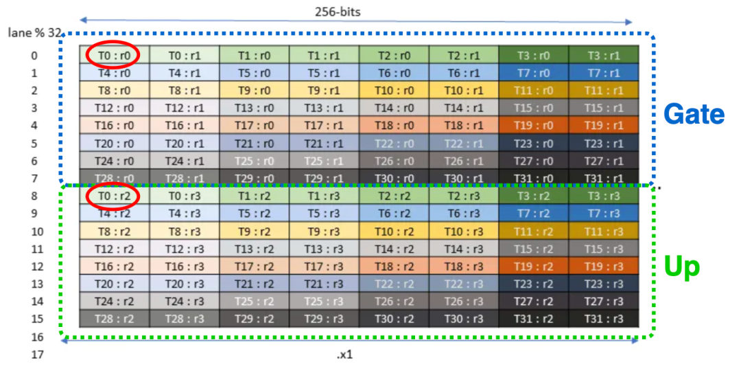
The SMEM base addresses for different stages differ by SMEM_{A,B}_SIZE_PER_STAGE bytes, so their desc.lo differs by a constant SMEM_{A,B}_SIZE_PER_STAGE / 16 (since the address field is already encoded with >>4). The purpose of the following two lines is to precompute the low halves of the descriptors for kNumStages stages into the registers of 32 lanes, with each lane storing the lo value for one stage. In the subsequent loop, ptx::exchange shuffles the value from the corresponding lane, avoiding repeated computation inside the loop. This is also why kNumStages <= 32.
uint32_t a_desc_lo = lane_idx < kNumStages ? a_desc.lo + lane_idx * SMEM_A_SIZE_PER_STAGE / 16 : 0u;
uint32_t b_desc_lo = lane_idx < kNumStages ? b_desc.lo + lane_idx * SMEM_B_SIZE_PER_STAGE / 16 : 0u;
Without this approach, the loop would require a multiply-add: a_desc.lo = base + stage_idx * stride. With this method, only one instruction is needed during the K loop:
const auto a_desc_base_lo = ptx::exchange(a_desc_lo, stage_idx);
const auto b_desc_base_lo = ptx::exchange(b_desc_lo, stage_idx);
ptx::exchange(reg, src_lane) corresponds to PTX shfl.idx.b32 — reading the a_desc_lo register value from lane stage_idx.
Comparing the two implementations:
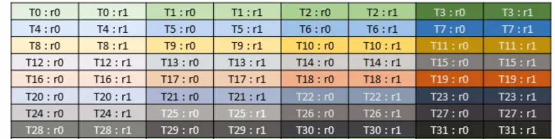
The K loop is the hottest path in the kernel (each block runs num_k_blocks × BLOCK_K / UMMA_K UMMA instructions). Every saved instruction accumulates, and shfl does not occupy the integer ALU, allowing better parallelism with tcgen05 emission, barrier waits, and other instructions.
4.4.6 MMA Instruction Shape Static Check
DG_STATIC_ASSERT(
    (UMMA_M == 64 && UMMA_N % 8 == 0 && 8 <= UMMA_N && UMMA_N <= 256) ||
    (UMMA_M == 128 && UMMA_N % 16 == 0 && 16 <= UMMA_N && UMMA_N <= 256) ||
    (UMMA_M == 256 && UMMA_N % 16 == 0 && 16 <= UMMA_N && UMMA_N <= 256),
    "Invalid MMA instruction shape");
This is the hardware constraint for the SM100 tcgen05.mma.cta_group::2.kind::mxf8f6f4 instruction. In this kernel, UMMA_M = 256 (LAYOUT_AD_M * 2) and UMMA_N = BLOCK_M, satisfying the third row of constraints.
| UMMA_M | UMMA_N Constraints |
|---|---|
| 64 | Multiple of 8, [8, 256] |
| 128 | Multiple of 16, [16, 256] |
| 256 | Multiple of 16, [16, 256] |
4.4.7 Persistent Block Iteration
The scheduler.for_each_block is still used here, consistent with TMA Producer A/B.
// Persistently schedule over blocks
uint32_t current_iter_idx = 0;
scheduler.for_each_block([&](const sched::BlockPhase& block_phase,
                              const uint32_t& local_expert_idx,
                              const uint32_t& num_k_blocks,
                              const uint32_t& m_block_idx,
                              const uint32_t& n_block_idx) {
These parameters only use num_k_blocks to drive the inner K loop.
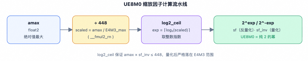
However, a global GEMM iteration counter current_iter_idx is added, which increments with each block and is never reset. It serves two purposes: mapping to the epilogue stage index accum_stage_idx = current_iter_idx % kNumEpilogueStages and the accumulator phase bit accum_phase = (current_iter_idx / kNumEpilogueStages) & 1.
4.4.7 Dynamic Update of UMMA_N Value
Due to the AB swap, UMMA_N corresponds to the M dimension of the activation. For the last tile of an expert, the number of tokens may be less than BLOCK_M.
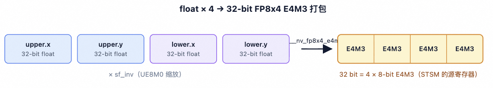 At this point, let UMMA compute only the
 valid_m rows; the remaining rows will be zero-filled and ignored by TMA's OOB handling.
// Dynamic update of UMMA N based on effective M
mma::sm100::update_instr_desc_with_umma_n(instr_desc, scheduler.template get_valid_m<true>());
// ref `mma/sm100.cuh`
void update_instr_desc_with_umma_n(cute::UMMA::InstrDescriptorBlockScaled& desc,
                                   const uint32_t& umma_n) {
    desc.n_dim_ = umma_n >> 3;  // UMMA_N is encoded in units of 8
}
4.4.8 TMEM Double Buffering
Before executing MMA, there is a wait on the TMEM empty barrier. Here, kNumEpilogueStages = 2 indicates there are two accumulator slots on TMEM, switching between two blocks. accum_stage_idx cycles between 0 and 1, and accum_phase flips every kNumEpilogueStages iterations.
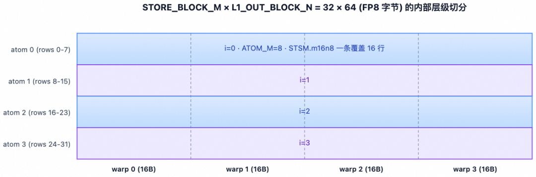
// Wait tensor memory empty barrier arrival
const auto accum_stage_idx = current_iter_idx % kNumEpilogueStages;
const auto accum_phase = (current_iter_idx++ / kNumEpilogueStages) & 1;
tmem_empty_barriers[accum_stage_idx]->wait(accum_phase ^ 1);
// All previous ordinary thread synchronization operations must be visible to the current thread
// before allowing emission of tcgen05 instructions (UTCCP, UMMA)
ptx::tcgen05_after_thread_sync();
For tmem_empty_barriers[i]->init(2 * kNumEpilogueThreads), the arrival count is initialized to 2 × total number of threads in the epilogue warpgroup. Both CTAs in a dual-CTA configuration must arrive (CTA × 2), and all epilogue threads within each CTA must arrive. After the epilogue warp finishes reading the accumulated results from TMEM, it collectively arrives at this barrier, releasing the accumulator slot. Meanwhile, the MMA warp must wait until all epilogue threads have finished reading before overwriting.
4.4.9 Empty Barrier Arrive
This step establishes a bidirectional synchronization mechanism. empty_barrier[i] is used to notify TMA Producer A/B warps, while tmem_full_barriers[k] is used to notify the Epilogue Warp.
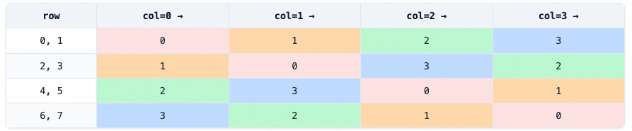
// Empty barrier arrival
auto empty_barrier_arrive = [&](const bool& do_tmem_full_arrive) {
    auto umma_arrive = [](const uint64_t* barrier) {
        constexpr uint16_t kCTAMask = (1 << 2) - 1;
        cutlass::arch::umma_arrive_multicast_2x1SM(barrier, kCTAMask);
    };
    umma_arrive(reinterpret_cast<uint64_t*>(empty_barriers[stage_idx]));
    // NOTES: the tensor memory accumulator pipeline has nothing to do with multicasting
    if (do_tmem_full_arrive)
        umma_arrive(reinterpret_cast<uint64_t*>(tmem_full_barriers[accum_stage_idx]));
    __syncwarp();
};
umma_arrive_multicast_2x1SM is essentially the PTX instruction tcgen05.commit.cta_group::2.mbarrier::arrive::one.multicast::cluster.shared::cluster wrapped by CUTLASS. Its purpose is to automatically arrive at the same barrier for all CTAs within the cluster after MMA completes. This is the official method for coordinating 2-CTA UMMA with smem barriers.
kCTAMask = (1 << 2) - 1 = 0b11: this bitmap indicates that both CTA 0 and CTA 1 within the cluster should receive the arrival.
Another detail: why multicast to release empty_barriers? empty_barriers[stage_idx] resides in each CTA's smem. TMA Load A/B warps wait on their respective CTA. The MMA warp on the leader CTA needs to notify the TMA warps on both CTAs that "the smem stage is empty and can be overwritten." Using the 2x1SM multicast primitive to arrive at both CTAs' barriers in one operation is more efficient than two separate ordinary arrivals.
Then it also waits on tmem_full_barriers[i]->init(1), whose arrival count is 1, requiring only one arrival from the MMA warp on the leader CTA. The do_tmem_full_arrive parameter is only true for the last K tile (k_block_idx == num_k_blocks - 1), meaning the epilogue is only notified that the accumulator is ready after the entire block's GEMM is complete. Note that although this barrier does not require multicast, the umma_arrive path is reused for code simplicity (the kCTAMask is redundant but harmless).
4.4.10 K Loop
The main loop is shown below, using the passed-in num_k_blocks as the loop control.
// Launch MMAs
#pragma unroll 2
for (uint32_t k_block_idx = 0; k_block_idx < num_k_blocks; advance_pipeline(k_block_idx)) {
Note that the advance_pipeline(k_block_idx) call in the for loop synchronously updates k_block_idx, stage_idx, and phase. The next iteration will see the new stage_idx pointing to the next smem stage.
Inside the loop, it first waits for TMA Producer A/B to complete:
// Wait TMA load completion
full_barriers[stage_idx]->wait(phase);
ptx::tcgen05_after_thread_sync();
After the arrival count of 4 (2 CTAs × 2 warps) plus all expect_tx bytes have arrived, the barrier flips the phase. Note that the phase waited on here is phase (not phase ^ 1 as used by the TMA warp), because the MMA warp and TMA warp use the phase in opposite ways — one is a consumer, the other a producer.
Next, it retrieves the pre-computed descriptor .lo field from Section 4.4.5. This line reads from lane_stage_idx to obtain the desc.lo base address corresponding to stage_idx:
const auto a_desc_base_lo = ptx::exchange(a_desc_lo, stage_idx);
const auto b_desc_base_lo = ptx::exchange(b_desc_lo, stage_idx);
Then it issues the UTCCP and UMMA instructions. On Blackwell, these instructions only need to be issued by a single thread, hence:
if (cute::elect_one_sync()) {
UTCCP
UTCCP is the TMEM load instruction on SM100 (actual name tcgen05.cp), specifically designed to
using cute_utccp_t = cute::SM100_UTCCP_4x32dp128bit_2cta;
#pragma unroll
for (uint32_t i = 0; i < SF_BLOCK_M / kNumUTCCPAlignedElems; ++ i) {
    auto smem_ptr = smem_sfa[stage_idx] + i * kNumUTCCPAlignedElems;
    mma::sm100::replace_smem_desc_addr(sf_desc, smem_ptr);
    cute_utccp_t::copy(sf_desc, kTmemStartColOfSFA + i * 4);
}
#pragma unroll
for (uint32_t i = 0; i < SF_BLOCK_N / kNumUTCCPAlignedElems; ++i) {
    auto smem_ptr = smem_sfb[stage_idx] + i * kNumUTCCPAlignedElems;
    mma::sm100::replace_smem_desc_addr(sf_desc, smem_ptr);
    cute_utccp_t::copy(sf_desc, kTmemStartColOfSFB + i * 4);
}
Let's first look at the loop tiling:
kNumUTCCPAlignedElems = 128, each UTCCP instruction covers 128 M elements;SF_BLOCK_M / 128iterations: batch-transfer the SF of allSF_BLOCK_MM elements to TMEM;- Each transfer goes to TMEM column
kTmemStartColOfSFA + i * 4, each UTCCP instance occupies 4 TMEM columns (corresponding to 128 / 32 = 4).
The SM100_UTCCP_4x32dp128bit_2cta instruction means:
4x32: 4 rows × 32 columns (4 UMMA_K groups × 32 M elements)dp128bit: 128-bit data path per transfer2cta: 2-CTA collaboration (consistent with UMMA 2-CTA)
Then replace_smem_desc_addr only replaces the start address field of the smem descriptor, preserving other fields (layout, SBO/LBO, etc.), which is much faster than reconstructing the entire descriptor.
void replace_smem_desc_addr(cute::UMMA::SmemDescriptor& desc,
                            const void* smem_ptr) {
    const auto uint_ptr = cute::cast_smem_ptr_to_uint(smem_ptr);
    desc.start_address_ = static_cast<uint16_t>(uint_ptr >> 4);
}
In the outer UMMA K-loop, each iteration advances BLOCK_K = 128 elements, issuing one TMA + UTCCP. In the inner K-loop, each iteration advances UMMA_K = 32 elements, issuing one UMMA instruction. Thus, one TMA tile corresponds to BLOCK_K / UMMA_K = 128 / 32 = 4 UMMA instructions, fully utilizing the data in TMEM.
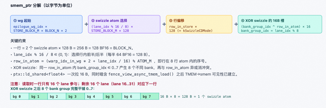
// Issue UMMA
#pragma unroll
for (uint32_t k = 0; k < BLOCK_K / UMMA_K; ++ k) {
    const auto runtime_instr_desc = mma::sm100::make_runtime_instr_desc_with_sf_id(instr_desc, k, k);
    a_desc.lo = mma::sm100::advance_umma_desc_lo<cute::UMMA::Major::K, LOAD_BLOCK_M, kSwizzleAMode,
                                                  a_dtype_t>(a_desc_base_lo, 0, k * UMMA_K);
    b_desc.lo = mma::sm100::advance_umma_desc_lo<cute::UMMA::Major::K, LOAD_BLOCK_N, kSwizzleBMode,
                                                  b_dtype_t>(b_desc_base_lo, 0, k * UMMA_K);
    ptx::SM100_MMA_MXF8F6F4_2x1SM_SS::fma(b_desc, a_desc, accum_stage_idx * UMMA_N,
                                           k_block_idx > 0 || k > 0, runtime_instr_desc,
                                           kTmemStartColOfSFB, kTmemStartColOfSFA);
}
In the loop, a runtime instruction descriptor is used to modify the SF index for the current UMMA call:
a_sf_id_ = b_sf_id_ = k, indicating the k-th SF atom in TMEM. Exactly every UMMA_K = 32 K elements corresponds to 1 SF slot.
const auto runtime_instr_desc = mma::sm100::make_runtime_instr_desc_with_sf_id(instr_desc, k, k);
// ref mma/sm100.cuh
uint64_t make_runtime_instr_desc_with_sf_id(cute::UMMA::InstrDescriptorBlockScaled desc,
                                            const uint32_t& sfa_id,
                                            const uint32_t& sfb_id) {
    desc.a_sf_id_ = sfa_id, desc.b_sf_id_ = sfb_id;
    return static_cast<uint64_t>(static_cast<uint32_t>(desc)) << 32;
}
Then advance desc.lo in the K direction:
a_desc.lo = mma::sm100::advance_umma_desc_lo<cute::UMMA::Major::K, LOAD_BLOCK_M, kSwizzleAMode,
                                              a_dtype_t>(a_desc_base_lo, 0, k * UMMA_K);
b_desc.lo = mma::sm100::advance_umma_desc_lo<cute::UMMA::Major::K, LOAD_BLOCK_N, kSwizzleBMode,
                                              b_dtype_t>(b_desc_base_lo, 0, k * UMMA_K);
// ref mma/sm100.cuh
// - `base` = stage base address, obtained from per-lane precomputed values
// - `offset = 0`: no offset in MN direction (single UMMA covers full LOAD*BLOCK*{M,N})
// - `k_idx = k * UMMA_K`: advance `k * 32` elements in K direction
uint32_t advance_umma_desc_lo(const uint32_t& base,
                              const uint32_t& offset,
                              const uint32_t& k_idx) {
    return base + (((offset + k_idx * get_umma_desc_stride_k<...>()) * sizeof(dtype_t)) >> 4u);
}
Then the PTX instruction is issued. Note the A/B swap: b_desc and a_desc are swapped, and kTmemStartColOfSFB and kTmemStartColOfSFA are also swapped.
ptx::SM100_MMA_MXF8F6F4_2x1SM_SS::fma(b_desc, a_desc, accum_stage_idx * UMMA_N,
                                       k_block_idx > 0 || k > 0, runtime_instr_desc,
                                       kTmemStartColOfSFB, kTmemStartColOfSFA);
Corresponding PTX:
tcgen05.mma.cta_group::2.kind::mxf8f6f4.block_scale [%tmem_c], %desc_a, %desc_b, %desc_hi, [%tmem_sfa], [%tmem_sfb], p (where p =
(scale_c != 0)). The complete parameter parsing is as follows:
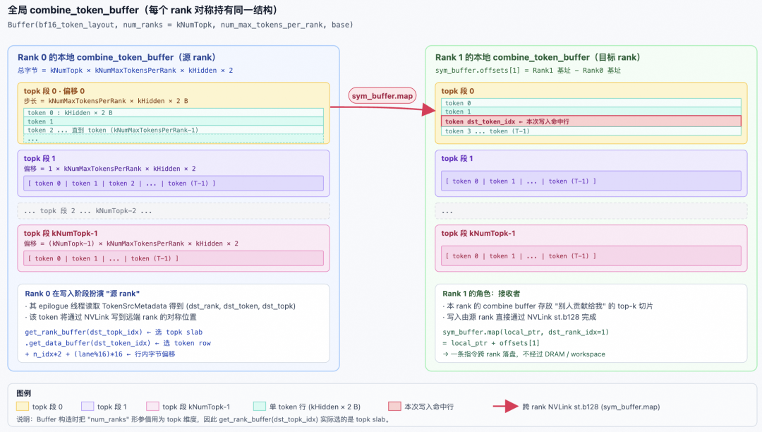
First UMMA (k_block_idx == 0 && k == 0): scale_c = false, the tcgen05 instruction uses scale::0, indicating overwriting the accumulator (initialization). All subsequent UMMAs: scale_c = true, using scale::1, indicating accumulation. This saves one traversal compared to first clearing the accumulator and then accumulating; the first UMMA automatically completes the clearing. Finally, warp synchronization is performed, and at the end of each K tile, a call is made to release empty_barriers[stage_idx], notifying the TMA warp that it can overwrite the smem stage, notifying TMA Producer A/B that they can overwrite SMEM.
__syncwarp();
// Commit to the mbarrier object
// No explicit `tcgen05.fence::before_thread_sync` is needed, as this is implicitly performed by `tcgen05.commit`
empty_barrier_arrive(k_block_idx == num_k_blocks - 1);
Finally, before exiting, there is a trailing barrier. Set tmem_empty_barriers to wait for the Epilogue to complete the computation of another TMEM buffer before executing the next MMA.
// To safely deconstruct barriers, we need another round of waits
if (current_iter_idx > 0) {
    const auto accum_phase_idx = ((current_iter_idx - 1) / kNumEpilogueStages) & 1;
    tmem_empty_barriers[(current_iter_idx - 1) % kNumEpilogueStages]->wait(accum_phase_idx);
}
4.4.11 Dual Pipeline Mechanism
Finally, let's emphasize how it interacts with the Producer A/B Warp and the Epilogue Warp through pipelining. The MMA warp simultaneously manages two sets of orthogonal pipelines:
GEMM smem pipeline (stage_idx, phase)
- Depth:
kNumStages(2/3/4, JIT adjustable) - Control variables:
stage_idx,phase(shared naming with TMA warp, advanced synchronously viaadvance_pipeline) - Barriers:
full_barriers[stage_idx](producer ← TMA warps, consumer ← MMA warp);empty_barriers[stage_idx](producer ← MMA warp, consumer ← TMA warps) - Lifecycle: Each K tile (BLOCK_K = 128 elements)
- Purpose: Overlap TMA load and UMMA computation across
kNumStagesstages.
TMEM accumulator pipeline (accum_stage_idx, accum_phase)
- Depth:
kNumEpilogueStages = 2(line 185) - Control variables:
accum_stage_idx,accum_phase(shared between MMA and epilogue) - Barriers:
tmem_full_barriers[accum_stage_idx](producer ← MMA warp, consumer ← epilogue);tmem_empty_barriers[accum_stage_idx](producer ← epilogue, consumer ← MMA warp) - Lifecycle: Each GEMM block (num_k_blocks K tiles)
- Purpose: Allow the MMA to compute block N+1 while the epilogue processes block N's accumulator in parallel (SwiGLU/quantization/TMA store).
4.5 Epilogue Warp
This is also a very complex warp to handle, covering three stages: L1 Epilogue, L2 Epilogue, and Combine.
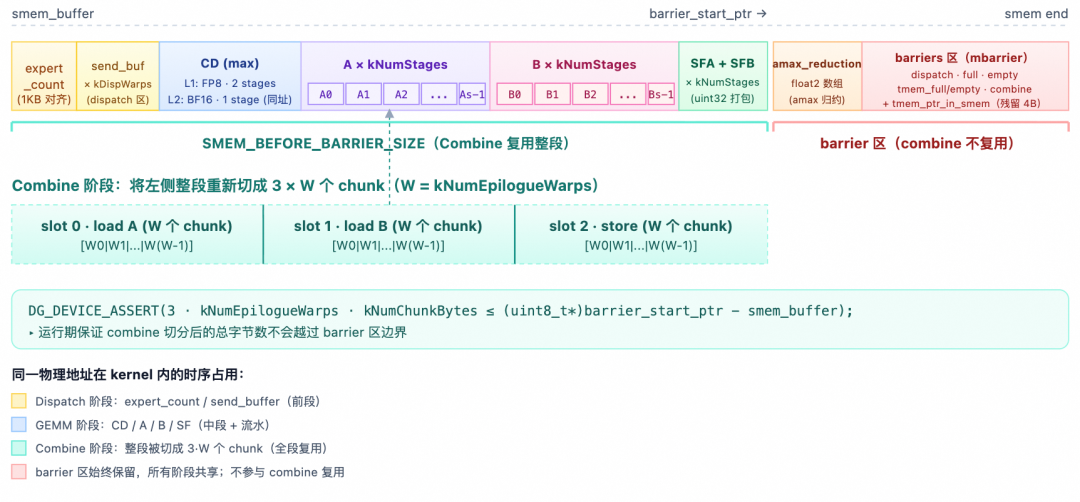
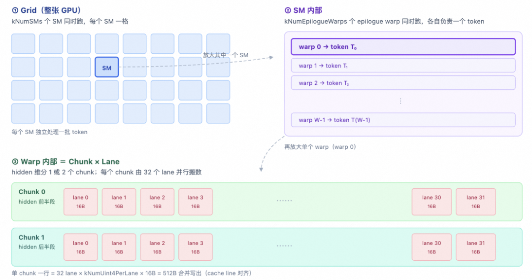
4.5.1 Initialization Phase
Some key constants are as follows. They indicate that the 2 epilogue warpgroups each handle BLOCK_M / 2 rows, the 4 warps/wg further divide the BN direction into 4 parts, and the M direction is further divided into STORE_BLOCK_M, then into ATOM_M = 8.
constexpr uint32_t WG_BLOCK_M = BLOCK_M / kNumEpilogueWarpgroups;  // Number of M rows per wg
constexpr uint32_t ATOM_M = 8;                                     // Minimum store granularity in M rows
constexpr uint32_t kNumBankGroupBytes = 16u;                       // Swizzle granularity = 16 bytes
constexpr uint32_t kNumAtomsPerStore = STORE_BLOCK_M / ATOM_M;     // Number of atoms per store block
The partitioning diagram is as follows:
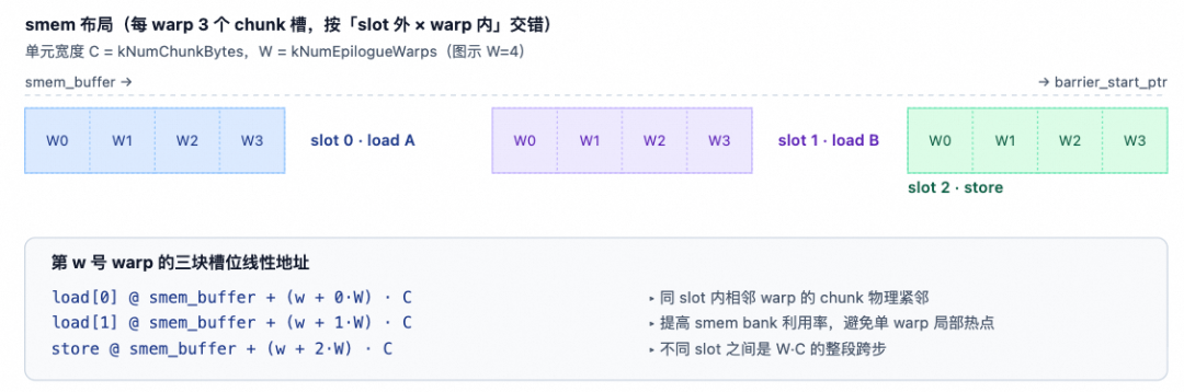
Therefore, there is a multi-level ID decomposition within the warp:
const auto epilogue_warp_idx = warp_idx - (kNumDispatchWarps + kNumMMANonEpilogueWarps);  // 0..kNumEpilogueWarps-1
const auto epilogue_wg_idx = epilogue_warp_idx / 4;                                       // Warpgroup number
const auto epilogue_thread_idx = epilogue_warp_idx * 32 + lane_idx;                        // Thread number within warpgroup
const auto warp_idx_in_wg = epilogue_warp_idx % 4;                                        // Warp number within wg
4.5.2 Synchronization with Dispatch Warp
Before starting, there is a synchronization with Dispatch. The reason for using unaligned is that the number of threads differs between Dispatch (usually 1 warpgroup, 128 threads) and Epilogue (2 warpgroups, 256 threads), and the warp boundaries are not aligned. Therefore, only the unaligned variant of bar.sync can be used:
ptx::sync_unaligned(kNumDispatchThreads + kNumEpilogueThreads, kDispatchWithEpilogueBarrierIdx);
Let's expand a bit on the entire synchronization mechanism between Dispatch and Epilogue. Their synchronization mechanism is relatively complex, as shown in the diagram below:
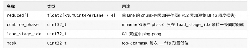
First synchronization: Mainly resolves SMEM ownership switching. The Dispatch's smem_send_buffers (pull TMA 1D landing area) and the Epilogue's combine stage combine_load_buffer/combine_store_buffer reuse the same segment of smem. During the Dispatch warp pull phase, smem is used. After synchronization, the Dispatch pull phase and the Epilogue phase (using smem_cd) for each GEMM block do not interfere with each other's smem usage.
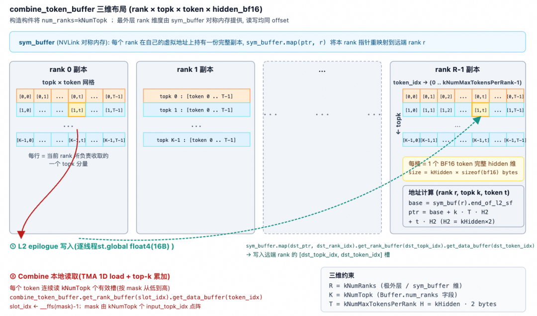
Second synchronization: Mainly resolves workspace ownership switching. The Epilogue Warp's combine stage needs to reuse smem (the interval from smem_buffer to barrier_start_ptr) as a combine chunk buffer. At this point, the Dispatch Warp needs to start cleaning up fields in the Workspace. It must wait until the final Combine stage begins before it can perform the cleanup, and this cleanup overlaps with the Combine computation.
4.5.3 Block Loop
Next, the Epilogue Warp also enters the scheduler.for_each_block loop. Within this loop, there are two branches to handle the L1 stage or L2 stage Epilogue computation.
uint32_t current_iter_idx = 0;
scheduler.for_each_block([&](const sched::BlockPhase& block_phase,
                              const uint32_t& local_expert_idx,
                              const uint32_t& num_k_blocks,
                              const uint32_t& m_block_idx,
                              const uint32_t& n_block_idx) {
    // Wait UMMA arrival
    const auto accum_stage_idx = current_iter_idx % kNumEpilogueStages;
    const auto accum_phase = (current_iter_idx++ / kNumEpilogueStages) & 1;
    tmem_full_barriers[accum_stage_idx]->wait(accum_phase);
    // Ensure that the results of ordinary thread synchronization are visible to subsequent tcgen05 instructions (`SM100_TMEM_LOAD_*`).
    ptx::tcgen05_after_thread_sync();

    // Offset calculation
    const uint32_t valid_m = ptx::exchange(scheduler.template get_valid_m<false>(), 0);
    const uint32_t pool_block_idx = scheduler.get_current_pool_block_offset() + m_block_idx;
    uint32_t m_idx = pool_block_idx * BLOCK_M;
    uint32_t n_idx = n_block_idx * BLOCK_N;
    // ...
    if (block_phase == sched::BlockPhase::Linear1) {
        /*----  L1 Epilogue Phase ---*/
    } else {
        /*----  L2 Epilogue Phase ---*/
    }
});
/*--- Combine ------*/
In the loop, we first wait for the L1/L2 MMA Warp to finish the MMA, and mark tmem_full_barriers[accum_stage_idx] as arrived. Here, tmem_full_barriers[i]->init(1), meaning only the MMA warp of the leader CTA needs to arrive once. Then, all epilogue warps from all CTAs wait on this same barrier: because the 2-CTA UMMA writes results to the TMEM of both CTAs; after the leader arrives once, the hardware guarantees that the TMEM on both sides is ready.
valid_m uses ptx::exchange(..., 0): it reads the value from lane 0 and broadcasts it to the entire warp—explicitly telling the compiler "this value is consistent across the entire warp and will not cause divergence". Then, based on pool_block_offset and the m_block_idx/n_block_idx input from the scheduler, it calculates the starting point of this block in the global coordinate system.
4.5.4 L1 Epilogue
L1 = post-processing of the first stage GEMM (gate + up projection) results. It mainly includes:
- Loading top-k weights, used to weight the results read from the Accumulator in TMEM within SwiGLU.
- Computing SwiGLU and multiplying by the top-k weights:
(silu(gate) * up) * weight. - Per-lane amax, then warp reduce + cross-warp reduce.
- Quantizing to FP8 E4M3, storing SF according to the UE8M0 scheme.
- Writing to
tensor_map_l1_output(i.e., the GMEM view ofl2_token_buffer) via TMA store. - Using
red_or_rel_gpu(l2_arrival_mask)atomic bitwise operation to announce "this N sub-block is ready", for TMA-Producer-A to load the L2 block.
4.5.4.1 Task Slicing
Since there are 8 Epilogue Warps, the BLOCK_M × BLOCK_N block produced by L1 MMA needs to be sliced across these 8 Warps. The slicing method was introduced in Section 4.5.1. We expand on it here: first, 4 Warps form a WarpGroup, so the entire Epilogue Warp typically has 2 WarpGroups (WG). They are split along the M dimension, with each WG responsible for WG_BLOCK_M = BLOCK_M / 2 data. Then, the 4 Warps within a WG are tiled along the N direction, with one Warp responsible for WG_BLOCK_M × (BLOCK_N / 4) data, as shown below:
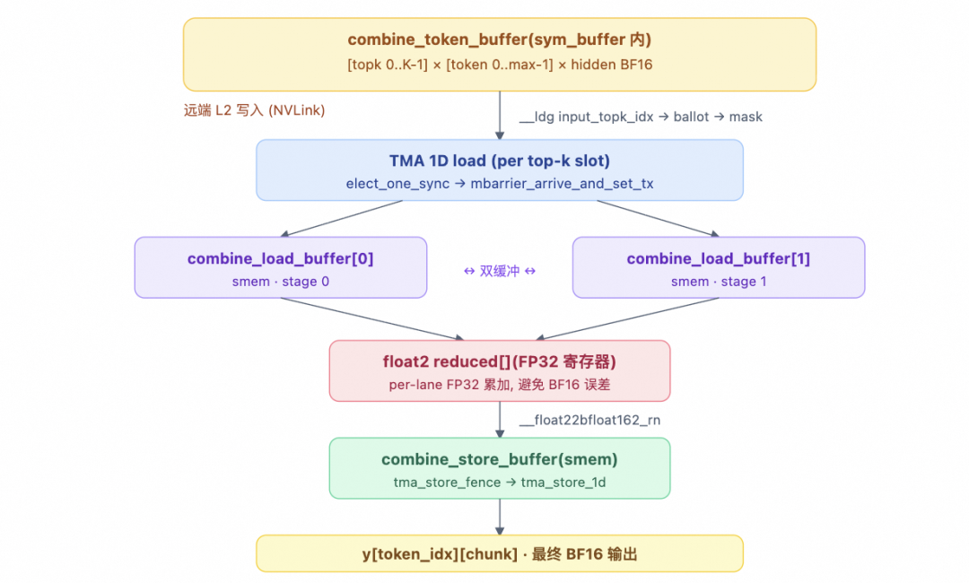
Then, within a Warp, the M dimension is further divided into WG_BLOCK_M / STOCK_BLOCK_M blocks of size STOCK_BLOCK_M × (BLOCK_N / 4). STOCK_BLOCK_M is determined by the heuristic scheduler based on the size of BLOCK_M.
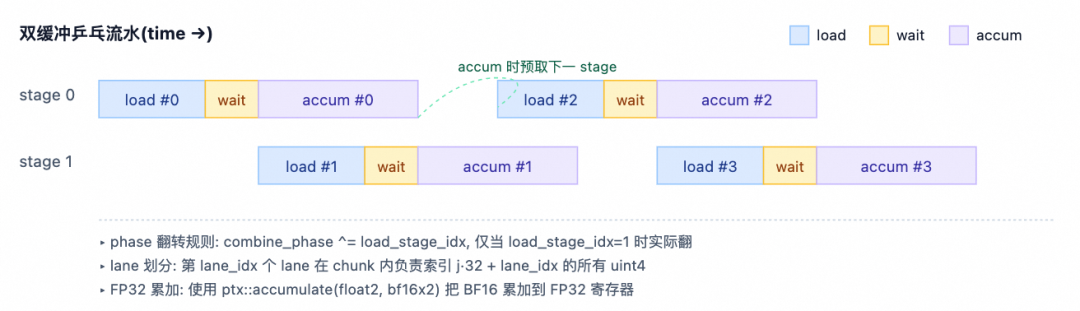
Outer loop: Iterating over Store Tiles
The code first has an outer loop based on STORE_BLOCK_M. In the loop, s is the Store Tile index.
float stored_cached_weight = 0;
#pragma unroll
for (uint32_t s = 0; s < WG_BLOCK_M / STORE_BLOCK_M; ++ s) {
    // If the starting row of the store tile exceeds valid_m, exit directly.
    // Here, epilogue_wg_idx is the WG number.
    if (epilogue_wg_idx * WG_BLOCK_M + s * STORE_BLOCK_M >= valid_m) {
        ptx::tcgen05_before_thread_sync();
        tmem_empty_barriers[accum_stage_idx]->arrive(0u);
        break;
    }
There is an optimization here: rows along the M axis that exceed valid_m are skipped directly. However, we still need to notify tmem_empty_barriers to release the TMEM accumulator slot; otherwise, the MMA warp will stall permanently. Note that tmem_empty_barriers[accum_stage_idx]->init(2 * kNumEpilogueThreads): the arrival count = 2 × total epilogue threads; every epilogue thread in every CTA must arrive once, so arrive(0u) is used here (each lane contributes 1).
Inner loop: Iterating over ATOM_M
Within a Store Tile, we continue to split along the M dimension into kNumAtomsPerStore = STORE_BLOCK_M / ATOM_M Atom Tiles, each with an M dimension of ATOM_M = 8 and a size of ATOM_M × (BLOCK_N / 4).
#pragma unroll
// For a store tile, unroll by ATOM_M; temporarily store SwiGLU results + amax
// for subsequent quantization
for (uint32_t i = 0; i < kNumAtomsPerStore; ++ i) {
    const uint32_t j = s * kNumAtomsPerStore + i;
    // Load weights from global into register cache per 32 tokens
    DG_STATIC_ASSERT(32 % ATOM_M == 0, "Invalid block size");
    /*------ ATOM_M Tile -----*/
}
There is another optimization here: for a warp of 32 lanes, if j * ATOM_M % 32 == 0 (i.e., every 4 atoms), the top-k weights for the next 32 M rows are all loaded into stored_cached_weight (1 per lane). The middle 3 atoms are fetched directly from register shuffles, so only 1 GMEM load is performed every 4 atoms.
4.5.4.2 Loading topk_weight
Here is the translation of chunk 33/50:
For the weights, the topk_weight weighting is directly absorbed into the SwiGLU computation process. It is sent in advance by the Dispatch Warp to the receiving end's l1_topk_weights_buffer. The loading code is as follows:
// Determine every 4 ATOM_M and when WG_BLOCK_M is divisible by 32, and does not exceed bounds, load into registers.
if((j * ATOM_M) % 32 == 0 && (WG_BLOCK_M % 32 == 0 || j * ATOM_M + lane_idx < WG_BLOCK_M)) {
    stored_cached_weight = *l1_topk_weights_buffer.get_data_buffer(m_idx + epilogue_wg_idx * WG_BLOCK_M + j * ATOM_M + lane_idx).get_base_ptr<float>();
}
// `ptx::exchange(cached, src_lane)`: Read weight from src_lane
const float2 weights = {
    ptx::exchange(stored_cached_weight, (j * ATOM_M) % 32 + (lane_idx % 4) * 2 + 0),
    ptx::exchange(stored_cached_weight, (j * ATOM_M) % 32 + (lane_idx % 4) * 2 + 1)
};
4.5.4.3 TMEM Load
In the TMEM address calculation:
accum_stage_idx * UMMA_N: Selects the current accumulator slot (column 0 or column UMMA_N).epilogue_wg_idx * WG_BLOCK_M: WarpGroup offset.j * ATOM_M: Atom offset.
Because the kernel uses AB-swap, UMMA_N corresponds to the M direction, so the column offset here represents the offset in the M direction. The loading method is as follows:
// Load from TMEM
uint32_t tmem_addr = accum_stage_idx * UMMA_N          // Select stage
                   + epilogue_wg_idx * WG_BLOCK_M      // WarpGroup selection half
                   + j * ATOM_M;                       // ATOM_M offset

uint32_t values[ATOM_M];
cute::SM100_TMEM_LOAD_16dp256b1x::copy(tmem_addr, values[0], values[1], values[2], values[3]);
cute::SM100_TMEM_LOAD_16dp256b1x::copy(tmem_addr | 0x00100000, values[4], values[5], values[6], values[7]);

// TMEM load is asynchronous; a barrier is needed to ensure subsequent regular register operations can see the load result
cutlass::arch::fence_view_async_tmem_load();
The TMEM load uses the SM100_TMEM_LOAD_16dp256b1x instruction. 16dp256b1x = 16 data paths × 256 bits × 1 atom. Each call loads 4 uint32 (per thread) into registers.
Why two TMEM loads?
Let's look at how the TMEM Accumulator is consumed after being split into ATOMs. TMEM itself is a 2D memory addressing architecture. Each CTA contains 512 columns and 128 rows, with each cell being 32 bits. Each Lane has 2KB, and the address uses a 32-bit format: Lane<31:16> Column<15:0>.
Due to AB Swap in UMMA, TMEM stores data in columns [0, UMMA_N) = BLOCK_M, and the number of rows occupied is BLOCK_N = 128 rows.
When performing WarpGroup splitting:
- Each WarpGroup processes WG_BLOCK_M = 64 columns, BLOCK_N rows.
- Continue splitting in the N dimension into 4 Warps. Each Warp processes WG_BLOCK_M = 64 columns, BLOCK_N / 4 = 32 rows.
- Continue splitting in the M dimension into Store Tiles and ATOM Tiles.
The ATOM Tile needs to process TMEM with ATOM_M = 8 columns, BLOCK_N / 4 = 32 rows, where the results are stored alternately between gate and up values in the row direction.
SM100_TMEM_LOAD_16dp256b1x processes 256-bits × 16 rows, which corresponds exactly to ATOM_M = 8 columns for FP32. To read all 32 rows, the offset for every 16 rows is 0x0010.0000. Therefore, tmem_addr and tmem_addr | 0x00100000 are used to load twice to fill the 32 rows.
The PTX documentation describes the matrix fragments for shape .16x256b.
Taking Thread 0 as an example, the first load of v[0] and v[2] forms a pair (gate, up). Thread 4 corresponds to the next pair of values for that token in the N direction.
4.5.4.4 TMEM Release
j is the global atom index within the wg. When j == WG_BLOCK_M / ATOM_M - 1, it indicates the last atom of this wg. At this point, the TMEM has been fully read, and the MMA warp can be notified to overwrite this accumulator slot.
// Signal tensor memory consumed on the last atom
if(j == WG_BLOCK_M / ATOM_M - 1) {
    ptx::tcgen05_before_thread_sync();
    tmem_empty_barriers[accum_stage_idx]->arrive(0u);
}
4.5.4.5 SwiGLU Activation Computation
The SwiGLU formula is as follows, and it also absorbs the topk_weight computation here:

Where silu(x) = x / (1 + exp(-x)) = x * sigmoid(x).
// Apply SwiGLU: silu(gate) * up
// Gate/up pairs: (0, 2), (1, 3), (4, 6), (5, 7)
auto fp32_values = reinterpret_cast<float*>(values);
#pragma unroll
for(uint32_t k = 0; k < 2; ++ k) {
    auto bf16_gate = __float22bfloat162_rn(make_float2(fp32_values[k * 4], fp32_values[k * 4 + 1]));
    auto bf16_up   = __float22bfloat162_rn(make_float2(fp32_values[k * 4 + 2], fp32_values[k * 4 + 3]));

    // Clamp
    if constexpr(kActivationClamp != cute::numeric_limits<float>::infinity()) {
        bf16_gate = __hmin2(bf16_gate, {kActivationClamp, kActivationClamp});
        bf16_up   = __hmax2(bf16_up,   {-kActivationClamp, -kActivationClamp});
        bf16_up   = __hmin2(bf16_up,   {kActivationClamp, kActivationClamp});
    }

    // SwiGLU
    auto gate = __bfloat1622float2(bf16_gate);
    auto neg_gate_exp = make_float2(kFastMath ? __expf(-gate.x) : expf(-gate.x),
                                    kFastMath ? __expf(-gate.y) : expf(-gate.y));
    const auto denom = __fadd2_rn({1.0f, 1.0f}, neg_gate_exp);
    if constexpr(kFastMath) {
        gate = __fmul2_rn(gate, {math::fast_rcp(denom.x), math::fast_rcp(denom.y)});
    } else {
        gate = {gate.x / denom.x, gate.y / denom.y};
    }
    const auto up = __bfloat1622float2(bf16_up);
    swiglu_values[i * 2 + k] = __fmul2_rn(__fmul2_rn(gate, up), weights);
}
First, TMEM reads FP32, using __float22bfloat162_rn to truncate to BF16, reducing the precision requirements for subsequent operations. Then there is a Clamp calculation, which is optional: if kActivationClamp is not infinity, gate is clamped to [-inf, +clamp], and up is clamped to [-clamp, +clamp]. The paper chooses 10. Then, for SwiGLU, the exponential operation exp(-gate) considers the computational cost of SFU on CUDA Cores. Here, fast math can be used for approximate calculation, then for a pair (gate.x, gate.y), compute exp(-gate) + 1 as the denominator. Similarly, fast_rcp can be used for approximate reciprocal to turn division into multiplication. Finally, silu(gate) x up x weight is completed with two __fmul2_rn calls. Next, write to swiglu_values[i * 2 + k] (float2): each atom produces 2 float2s, accumulating 4 FP32 values. Note why there are two rounds with k = 0/1: values[0..3] are group 0 gate/up, and values[4..7] are group 1. Each 8 elements = 2 groups (gate.x, gate.y, up.x, up.y), hence the k loop runs 2 times.
4.5.4.6 Amax Reduction + FP8 Quantization
This is essentially a three-layer max reduction: register (4 lanes) → smem shared array → cross-warp pairing (warp ⊕ 1).
First layer: warp 4-lane reduction code:
// Amax reduction
amax_values[i].x = math::warp_reduce<4,true>(cute::max(cute::abs(swiglu_values[i *2+0].x), cute::abs(swiglu_values[i *2+1].x)),math::ReduceMax<float>());
amax_values[i].y = math::warp_reduce<4,true>(cute::max(cute::abs(swiglu_values[i *2+0].y), cute::abs(swiglu_values[i *2+1].y)),math::ReduceMax<float>());
Here, we explain math::warp_reduce<4, true>. Within an ATOM Tile, in the TMEM load instruction, different columns represent different tokens. Thus, the thread stride for the same token in the N dimension is 4, as shown below: T0, T4, T8, T12, T16, T20, T24, T26, T28 represent the values of one token along the hidden dimension.
The warp_reduce implementation is as follows, along with a simple test:
template<typename T>
struct ReduceMax {
    __device__ T operator()(T a, T b) const {
        return a > b ? a : b;
    }
};

template<uint32_t kNumLanesPerGroup, bool kIntergroupReduce, typename T, typename Op>
__device__ T warp_reduce(T value, Op op) {
    constexpr uint32_t mask = 0xffffffff;
    if constexpr (kIntergroupReduce) {
        if constexpr (kNumLanesPerGroup <= 1) value = op(value, __shfl_xor_sync(mask, value, 1));
        if constexpr (kNumLanesPerGroup <= 2) value = op(value, __shfl_xor_sync(mask, value, 2));
        if constexpr (kNumLanesPerGroup <= 4) value = op(value, __shfl_xor_sync(mask, value, 4));
        if constexpr (kNumLanesPerGroup <= 8) value = op(value, __shfl_xor_sync(mask, value, 8));
        if constexpr (kNumLanesPerGroup <= 16) value = op(value, __shfl_xor_sync(mask, value, 16));
    } else {
        if constexpr (kNumLanesPerGroup >= 32) value = op(value, __shfl_xor_sync(mask, value, 16));
        if constexpr (kNumLanesPerGroup >= 16) value = op(value, __shfl_xor_sync(mask, value, 8));
        if constexpr (kNumLanesPerGroup >= 8) value = op(value, __shfl_xor_sync(mask, value, 4));
        if constexpr (kNumLanesPerGroup >= 4) value = op(value, __shfl_xor_sync(mask, value, 2));
        if constexpr (kNumLanesPerGroup >= 2) value = op(value, __shfl_xor_sync(mask, value, 1));
    }
    return value;
}

__global__ void verifyWarpReduceMaxKernel(const float* input, float* output) {
    int tid = blockIdx.x * blockDim.x + threadIdx.x;
    float my_val = tid * 1.0;
    float warp_max = warp_reduce<4, true>(my_val, ReduceMax<float>());
    printf(" tid %d , %f \n", tid, warp_max);
    output[tid] = warp_max;
}
The output shows that for tid = [0, 4, 8, 12, 16, 20, 24, 28], the max value is 28. The other three groups behave similarly. This achieves the maximum value along the hidden dimension of the token.
Second layer: Write to Smem
smem_amax_reduction is also stored in units of float2. epilogue_warp_idx is the warp index within a WarpGroup. During computation, since float2 only needs * (STORE_BLOCK_M / 2) plus the atom tile offset, and finally the index within the atom tile, and because the previous step used broadcast mode (e.g., tid = [0, 4, 8, 12, 16, 20, 24, 28] all have the max value), only the first 4 lanes need to be processed.
if (lane_idx < 4)
    smem_amax_reduction[epilogue_warp_idx * (STORE_BLOCK_M / 2) + i * (ATOM_M / 2) + lane_idx] = amax_values[i];
__syncwarp();
Then wait for the TMA store to release smem.
// Wait shared memory release from previous TMA store
// And fence `smem_amax_reduction`
const uint32_t tma_stage_idx = s % kNumTMAStoreStages;
ptx::tma_store_wait<kNumTMAStoreStages - 1>();
ptx::sync_aligned(128, kEpilogueWGBarrierStartIdx + epilogue_wg_idx);
Third layer: Cross-warp pairing to take max (warp ⊕ 1) After SwiGLU multiplies gate * up, two adjacent warps
outputs share the same BF16 swizzle ATOM (i.e., in the BF16 view, the 8+8=16 rows of two warps belong to the same stmatrix unit), so they must use the same scaling factor; otherwise, dequantization cannot restore the original values. Therefore, the XOR 1 (pair: warp0↔warp1, warp2↔warp3) is used here to retrieve the half amax written by the partner warp, and take the max. As in the second layer earlier, each warp writes 4 float2 values into its own slot epilogue_warp_idx*(STORE_BLOCK_M/2) + i*(ATOM_M/2) + [0..3].
#pragma unroll
for (uint32_t i = 0; i < kNumAtomsPerStore; ++ i) {
    // Reduce amax
    // `^ 1` Pair the current warp with its "neighbor warp".
    const float2 wp_amax = smem_amax_reduction[(epilogue_warp_idx ^ 1) * (STORE_BLOCK_M / 2) + i * (ATOM_M / 2) + lane_idx % 4];
    amax_values[i].x = cute::max(amax_values[i].x, wp_amax.x);
    amax_values[i].y = cute::max(amax_values[i].y, wp_amax.y);
4.5.4.7 FP8 Quantization
- Compute UE8M0 scaling factor
As shown below:
// Calculate SF
float2 sf, sf_inv;
math::get_e4m3_sf_and_sf_inv(amax_values[i], sf, sf_inv);

/*--------- ref: get_e4m3_sf_and_sf_inv -----------*/
template <bool kUseUE8M0 = true>
CUTLASS_DEVICE void get_e4m3_sf_and_sf_inv(const float2& amax, float2& sf, float2& sf_inv) {
    DG_STATIC_ASSERT(kUseUE8M0, "Must use UE8M0");
    const float2 finfo_factor = {1.0/448.0, 1.0/448.0}; // E4M3 max=448
    const auto scaled = __fmul2_rn(amax, finfo_factor); // amax / 448
    const auto exp_x = fast_log2_ceil(scaled.x); // ceiling log2
    const auto exp_y = fast_log2_ceil(scaled.y);
    sf.x = fast_pow2(exp_x), sf_inv.x = fast_pow2(-exp_x); // 2^e — for dequantization, 2^-e — for quantization
    sf.y = fast_pow2(exp_y), sf_inv.y = fast_pow2(-exp_y);
}
Here, UE8M0 = retains only the 8-bit exponent of FP32, with no mantissa and no sign**. Therefore, SF must be an integer power of 2. log2_ceil is used here to ensure amax * sf_inv ≤ 448, i.e., the quantized value falls strictly within the representable range of E4M3.
- Cast to FP8 E4M3
Then cast the values to FP8 E4M3. First, use sf_inv to scale the 4 floats into the E4M3 range, then use __nv_fp8x4_e4m3 to pack the 4 floats into a single 32-bit register (4 bytes = 4 E4M3 values). This is exactly the 32-bit source data required by the subsequent STSM.
// Cast
const float2 upper = __fmul2_rn(swiglu_values[i * 2 + 0], sf_inv);
const float2 lower = __fmul2_rn(swiglu_values[i * 2 + 1], sf_inv);
const auto fp8x4_values = __nv_fp8x4_e4m3(make_float4(upper.x, upper.y, lower.x, lower.y));
- STSM write to shared memory
From the perspective of STORE_BLOCK, the layout is as follows:
The STSM instruction used for storage is stmatrix.sync.aligned.m16n8.x1.trans.shared.b8 [addr], {reg};
Where m16n8.x1.trans: a warp cooperatively writes a 16×8 8-bit matrix transposed to smem, with each lane providing 32 bits; here, it actually writes 16 rows × 8 columns of FP8 (128 bytes) at once.
When locating in smem, first position based on the Warpgroup id and the i-th ATOM Tile within the store tile.
// STSM
uint32_t row = lane_idx; // 0..31
uint32_t col = warp_idx_in_wg; // 0..3, corresponding to 4 16B segments
const auto smem_ptr = smem_cd[tma_stage_idx]
    + epilogue_wg_idx * STORE_BLOCK_M * L1_OUT_BLOCK_N   // locate which WarpGroup
    + i * ATOM_M * L1_OUT_BLOCK_N                        // locate which ATOM
    + row * L1_OUT_BLOCK_N                               // row offset, each row (BLOCK_N / 2 = 64) bytes
    + (col ^ (row / 2)) * kNumBankGroupBytes;            // column offset + swizzle

ptx::SM100_U8x4_STSM_T<__nv_fp8x4_e4m3>::copy(fp8x4_values, smem_ptr);
The XOR Swizzle indicates that the physical positions of the 4 16B bank-groups within the same row shift with the row number, as shown in the figure below:
4.5.4.8 Write L2 input SF
// - After pairing, the SF of the two warps is synchronized; only even warps write.
// - Every 4 lanes share 1 SF (already broadcast within the 4 lanes) — so `lane < 4` each lane writes 2 rows (sf.x + sf.y).
if (warp_idx_in_wg % 2 == 0 and lane_idx < 4) {
    const uint32_t k_idx = n_block_idx * 2 + warp_idx_in_wg / 2;
    const uint32_t k_uint_idx = k_idx / 4, byte_idx = k_idx % 4;
    const uint32_t mn_stride = kNumPaddedSFPoolTokens * sizeof(uint32_t);
    const auto sf_base_ptr = l2_sf_buffer.get_base_ptr<uint8_t>();
    const uint32_t token_base_idx = epilogue_wg_idx * WG_BLOCK_M + s * STORE_BLOCK_M + i * ATOM_M;
    __builtin_assume(token_base_idx < BLOCK_M);
    const auto sf_pool_token_idx = scheduler.get_current_pool_block_offset() * SF_BLOCK_M
        + m_block_idx * SF_BLOCK_M + transform_sf_token_idx(token_base_idx) + (lane_idx * 2) * 4;
    const auto sf_addr = k_uint_idx * mn_stride + sf_pool_token_idx * sizeof(uint32_t) + byte_idx;
    sf_base_ptr[sf_addr] = (*reinterpret_cast<const uint32_t*>(&sf.x) >> 23); // In the fp32 bit pattern, bits 23–30 are
exponent(8 bit) // Shift right 23 bits to get bits = sign(1) + exp(8) = 9 bits, but sign is always 0,
// so `>> 23` yields the 8-bit value of `exp`;
// Write to `uint8_t`: automatically truncates, keeping only the lower 8 bits = UE8M0 byte.
sf_base_ptr[sf_addr + 4 * sizeof(uint32_t)] =
    (*reinterpret_cast<const uint32_t*>(&sf.y) >> 23);
}

#### 4.5.4.9 TMA store L1 output

Finally, issue the TMA:

```cuda
if (warp_idx_in_wg == 0 && cute::elect_one_sync()) {
    uint32_t out_n_idx = n_block_idx * L1_OUT_BLOCK_N;
    cute::tma_store_fence();
    cute::SM90_TMA_STORE_2D::copy(
        &tensor_map_l1_output,
        smem_cd[tma_stage_idx] + epilogue_wg_idx * STORE_BLOCK_M * L1_OUT_BLOCK_N,
        out_n_idx,
        m_idx + epilogue_wg_idx * WG_BLOCK_M + s * STORE_BLOCK_M);
    cute::tma_store_arrive();
}
__syncwarp();
Then notify L2 via l2_arrive_mask:
// Notify L2
ptx::tma_store_wait<0>();
ptx::sync_aligned(kNumEpilogueThreads, kEpilogueFullBarrierIdx);
if (epilogue_warp_idx == 0 && cute::elect_one_sync()) {
    DG_STATIC_ASSERT(L2_SHAPE_K <= 64 * L1_OUT_BLOCK_N,
                     "L2 shape K is too large");
    ptx::red_or_rel_gpu(workspace.get_l2_arrival_mask_ptr(pool_block_idx),
                        1ull << n_block_idx);
}
__syncwarp();
4.5.5 L2 Epilogue
L2 = post-processing of the second stage GEMM (down projection) results. Key tasks:
- Read accumulators from TMEM and convert to BF16
- Write to
smem_cd_l2via STSM - Determine the remote rank/token/topk position for each row based on
token_src_metadata - Write directly to the remote
combine_token_buffer[topk_idx][token_idx]via NVLink (sym_buffer.map)
4.5.5.1 TMEM Read
The task partitioning is the same as the L1 Epilogue, and the TMEM read is also essentially identical:
#pragma unroll
for (uint32_t s = 0; s < WG_BLOCK_M / STORE_BLOCK_M; ++ s) {
    if (epilogue_wg_idx * WG_BLOCK_M + s * STORE_BLOCK_M >= valid_m) {
        ptx::tcgen05_before_thread_sync();
        tmem_empty_barriers[accum_stage_idx]->arrive(0u);
        break;
    }
    #pragma unroll
    for (uint32_t i = 0; i < STORE_BLOCK_M / ATOM_M; ++ i) {
        uint32_t tmem_addr = accum_stage_idx * UMMA_N +
                             epilogue_wg_idx * WG_BLOCK_M +
                             s * STORE_BLOCK_M + i * ATOM_M;
        uint32_t values[ATOM_M];
        cute::SM100_TMEM_LOAD_16dp256b1x::copy(tmem_addr,
                                               values[0], values[1], values[2], values[3]);
        cute::SM100_TMEM_LOAD_16dp256b1x::copy(tmem_addr | 0x00100000,
                                               values[4], values[5], values[6], values[7]);
        cutlass::arch::fence_view_async_tmem_load();
Then wait and release TMEM:
        // Wait shared memory release from previous NVLink store
        if (i == 0 && s > 0)
            ptx::sync_aligned(128, kEpilogueWGBarrierStartIdx + epilogue_wg_idx);

        // Signal tensor memory consumed
        if (s == WG_BLOCK_M / STORE_BLOCK_M - 1 &&
            i == STORE_BLOCK_M / ATOM_M - 1) {
            ptx::tcgen05_before_thread_sync();
            tmem_empty_barriers[accum_stage_idx]->arrive(0u);
        }
4.5.5.2 Convert to BF16 and Store to SMEM
        // Store into shared memory
        uint32_t row = lane_idx % 8;
        uint32_t col = (epilogue_warp_idx % 2) * 4 + lane_idx / 8;
        const auto smem_ptr = smem_cd_l2 +
            epilogue_wg_idx * STORE_BLOCK_M * BLOCK_N * static_cast<uint32_t>(sizeof(nv_bfloat16)) +
            (warp_idx_in_wg / 2) * STORE_BLOCK_M * kSwizzleCDMode +
            i * ATOM_M * kSwizzleCDMode +
            row * (kNumBankGroupBytes * 8) +
            (col ^ row) * kNumBankGroupBytes;

        ptx::SM90_U32x4_STSM_T<uint32_t>::copy(
            math::cast_into_bf16_and_pack(values[0], values[1]),
            math::cast_into_bf16_and_pack(values[2], values[3]),
            math::cast_into_bf16_and_pack(values[4], values[5]),
            math::cast_into_bf16_and_pack(values[6], values[7]),
            smem_ptr);
Then wait and recalculate row_in_atom and bank_group_idx because the layout for NVLink writes differs from the STSM layout (one warp corresponds to one row):
        // Wait shared memory ready
        ptx::sync_aligned(128, kEpilogueWGBarrierStartIdx + epilogue_wg_idx);

        // Write into remote buffers
        const uint32_t row_in_atom = (warp_idx_in_wg * 2 + lane_idx / 16) % ATOM_M;
        const uint32_t bank_group_idx = lane_idx % 8;
4.5.5.3 NVLink Remote Write
Each epilogue warpgroup (4 warps = 128 threads) is responsible for writing STORE_BLOCK_M rows. The allocation in this stage differs from the STSM storage stage: each warp exclusively owns several complete rows (one warp per row), and each row is divided into 16 float4 by 16 lanes (i.e., 16 × 8 = 128 BF16 = BLOCK_N).
row_in_store and m_idx_in_block are calculated as follows:
#pragma unroll
// Each warp is responsible for `kNumRowsPerWarp = STORE_BLOCK_M / 8` rows
for (uint32_t j = 0; j <
for (uint32_t j = 0; j < kNumRowsPerWarp; ++j) {
    const uint32_t row_in_store = j * 8 + warp_idx_in_wg * 2 + lane_idx / 16;
    const uint32_t m_idx_in_block = epilogue_wg_idx * WG_BLOCK_M + s * STORE_BLOCK_M + row_in_store;
Then, handle the exclusion of padding rows, exit early, and for valid tokens, look up the source routing information written during the dispatch phase.
    // Skip rows that belong to padding (exceeding the actual token count for this expert)
    if (m_idx_in_block >= valid_m)
        break;

    // Read the write-back metadata written during the dispatch phase: destination rank / token / topk slot
    const auto src_metadata = *workspace.get_token_src_metadata_ptr(m_idx + m_idx_in_block);
    const uint32_t dst_rank_idx = src_metadata.rank_idx;
    const uint32_t dst_token_idx = src_metadata.token_idx;
    const uint32_t dst_topk_idx = src_metadata.topk_idx;
The pointer calculation for smem is essentially a four-term addition: base address + this wg's large block + first/second half atom within a row + row number + XOR'd 16 B slot.
    const auto smem_ptr =
        smem_cd_l2                                                                    // ① warpgroup's smem base address
        + epilogue_wg_idx * STORE_BLOCK_M * BLOCK_N * 2                               // ② This wg's STORE_BLOCK_M × BLOCK_N large block (×2 for BF16)
        + (lane_idx % 16 / 8) * STORE_BLOCK_M * kSwizzleCDMode                        // ③ First/second half atom within a row (two 128 B segments)
        + row_in_store * kSwizzleCDMode                                                // ④ Which row × 128 B
        + (bank_group_idx ^ row_in_atom) * kNumBankGroupBytes;                         // ⑤ XOR-swizzled 16 B slot (= 1 float4)

    // Read 16B packed float4 from smem
    const auto packed = ptx::ld_shared(reinterpret_cast<float4*>(smem_ptr));
Constants and intermediate values involved:
bank_group_idx = lane_idx % 8— 8 bank groups per cycle (each bg = 4 banks × 4 B = 16 B)row_in_atom = (warp_idx_in_wg * 2 + lane_idx / 16) % ATOM_M,ATOM_M = 8row_in_store = j * 8 + warp_idx_in_wg * 2 + lane_idx / 16— row index within the entireSTORE_BLOCK_MkSwizzleCDMode = 128 B: byte count of one swizzle atom (= 64 BF16)kNumBankGroupBytes = 16 B: size of one float4 (= 8 BF16)
The structure and addressing of combine_token_buffer are as follows:
    // Map the pointer of this rank to the remote rank's NVLink address via sym_buffer.map
    // Finally write to dst_rank's
    // combine_token_buffer[dst_topk][dst_token] corresponding output
    const auto dst_token = combine_token_buffer.get_rank_buffer(dst_topk_idx)   // 1. topk dimension
                               .get_data_buffer(dst_token_idx);                 // 2. token slot for that topk

    // 3. Select hidden slice
    const auto dst_ptr = math::advance_ptr<float4>(
        dst_token.get_base_ptr(),
        n_idx * static_cast<uint32_t>(sizeof(nv_bfloat16)) +
        (lane_idx % 16) * static_cast<uint32_t>(sizeof(float4)));

    *sym_buffer.map(dst_ptr, dst_rank_idx) = packed;
}
Final epilogue global synchronization:
// Ensure the next epilogue round does not read/write smem before this
ptx::sync_aligned(kNumEpilogueThreads, kEpilogueFullBarrierIdx);
4.5.6 Combine Phase
This is the final segment of the Mega-MoE persistent kernel. It performs top-k reduction per token on the "weighted BF16 partial sums" written back to combine_token_buffer by each rank during the L2 Epilogue phase, and finally writes the global output y[num_tokens, hidden].
4.5.6.1 Preprocessing and Synchronization
First, release TMEM and perform an NVLink barrier, waiting for all ranks to write data into combine_token_buffer. Then synchronize again with the dispatch warp, because the Combine phase needs to occupy SMEM. After synchronization, the SMEM management handover is complete, and the dispatch phase can safely clean up the workspace. The entire SMEM reuse is shown below:
// Release TMEM: both CTAs must be called by the same logical warp id
if (epilogue_warp_idx == 0) Allocator().free(0, kNumTmemCols);

// NVLink barrier (grid sync + cross-rank signal + grid sync): ~4 us
// Global synchronization before Combine: cross-SM grid sync + cross-rank NVLink barrier + another
// grid sync, ensuring all ranks' L2 outputs have been written to their respective combine buffers
comm::nvlink_barrier<kNumRanks, kNumSMs, kNumEpilogueThreads,
                     kEpilogueGridSyncIndex, kBeforeCombineReduceBarrierTag>(
    workspace, sym_buffer, sm_idx, epilogue_thread_idx, [&]() {
        ptx::sync_aligned(kNumEpilogueThreads, kEpilogueFullBarrierIdx);
    });

// Synchronize with dispatch warp: ensure the dispatch warp can safely clean up the workspace
ptx::sync_unaligned(kNumDispatchThreads + kNumEpilogueThreads,
                    kDispatchWithEpilogueBarrierIdx);
4.5.6.2 Work Partitioning
The loop that advances through all tokens is as follows:
for (uint32_t token_idx = sm_idx * kNumEpilogueWarps + epilogue_warp_idx;
     token_idx < num_tokens;
     token_idx += kNumSMs * kNumEpilogueWarps) { ... }
The step size is kNumSMs * kNumEpilogueWarps, meaning the overall processing is done at a granularity of one warp per token. Within a warp, the hidden dimension is further split into 1 or 2 chunks, and the 32 lanes process them in parallel, as shown below:
The variables related to chunk splitting are as follows. Overall, there are 3 slots in SMEM, two for reading and one for writing. A token is split into 1 or 2 chunks, constrained by SMEM capacity. Only splitting into 1 or 2 chunks is allowed to avoid creating chunks that are too small. Finally, based on the hidden dimension information, the amount of data processed by each lane is calculated.
constexpr uint32_t kNumHiddenBytes = kHidden * sizeof(nv_bfloat16);
constexpr uint32_t kNumChunkSlots = 3; // 2 load + 1 store
constexpr uint32_t kNumMaxRegistersForBuffer = 128;
constexpr uint32_t kNumChunks =
    (kNumChunkSlots * kNumEpilogueWarps * kNumHiddenBytes <= SMEM_BEFORE_BARRIER_SIZE &&
     kHidden <= 32 * kNumMaxRegistersForBuffer) ? 1 : 2;
constexpr uint32_t kNumChunkBytes  = kNumHiddenBytes / kNumChunks;
constexpr uint32_t kNumChunkUint4  = kNumChunkBytes / sizeof(uint4);
constexpr uint32_t kNumUint4PerLane = kNumChunkUint4 / 32; // Number of uint4 per lane
There are also some static checks during compilation:
kHidden % kNumChunks == 0(divisible)3 * kNumEpilogueWarps * kNumHiddenBytes / kNumChunks ≤ SMEM_BEFORE_BARRIER_SIZE(fits in SMEM)kNumChunkBytes % 16 == 0(satisfies TMA 1D 16B alignment)kNumChunkUint4 % 32 == 0(at least one uint4 per lane)kNumTopk ≤ 32(a single warp can accommodate all top-k slots)
A runtime SMEM out-of-bounds check is also performed:
DG_DEVICE_ASSERT(kNumChunkSlots * kNumEpilogueWarps * kNumChunkBytes <=
                 static_cast<uint32_t>(reinterpret_cast<uint8_t*>(barrier_start_ptr) - smem_buffer));
4.5.6.3 Memory Layout
SMEM Layout
Each epilogue warp is allocated 3 chunk slots: slots 0/1 are for load double buffering, and slot 2 is for store. Multiple warps are interleaved using the index (warp_idx + slot * kNumEpilogueWarps) to fully utilize SMEM.
This stripe pattern, with slot as the outer dimension and warp as the inner dimension, places the same-slot blocks of adjacent warps physically adjacent in SMEM. This maximizes bank utilization and avoids local hotspots for a single warp.
const auto combine_load_buffer = utils::PatternVisitor([&](const uint32_t& i) {
    return math::advance_ptr<uint4>(smem_buffer,
                                    (epilogue_warp_idx + i * kNumEpilogueWarps) * kNumChunkBytes);
});
const auto combine_store_buffer = math::advance_ptr<uint4>(smem_buffer,
                                    (epilogue_warp_idx + kNumEpilogueWarps * 2) * kNumChunkBytes);
Each warp then has 2 mbarriers (corresponding to load slots 0/1). During kernel initialization:
combine_barriers[i]->init(1) // L461
The arrival count is 1 (one TMA completion = one arrive), and the total is kNumEpilogueWarps * 2, matching the number of load slots in the stripe.
auto combine_load_barriers = utils::PatternVisitor([&](const uint32_t& i) {
    return combine_barriers[i + epilogue_warp_idx * 2];
});
Register Layout
Combine_token_buffer Structure
The Combine Epilogue needs to process data from the L2 epilogue stage, which writes to the same buffer on the target rank via sym_buffer.map(dst_ptr, dst_rank_idx). This stage reads its own rank's copy. Its dimensions are (kNumTopk, kNumMaxTokensPerRank), with each slot containing one BF16 token (hidden dimension). The physical location is within sym_buffer (symmetric memory), with the same offset for all ranks.
const auto combine_token_buffer = layout::Buffer(bf16_token_layout, kNumTopk, kNumMaxTokensPerRank,
                                                  l2_sf_buffer.get_end_ptr());
4.5.6.4 Main Loop Flow
The entire loop iterates over all tokens at the warp granularity, with a step size of kNumSMs * kNumEpilogueWarps. For specific work partitioning details, refer to Section 4.5.6.2.
for (uint32_t token_idx = sm_idx * kNumEpilogueWarps + epilogue_warp_idx;
     token_idx < num_tokens;
     token_idx += kNumSMs * kNumEpilogueWarps) { ... }
Top-k Slot Reading
Each lane reads one top-k slot (which stores the target rank ID, with -1 indicating unused).
const int stored_topk_slot_idx =
    lane_idx < kNumTopk
        ? static_cast<int>(__ldg(input_topk_idx_buffer.get_base_ptr<int64_t>() +
                                 token_idx * kNumTopk + lane_idx))
        : -1;
const uint32_t total_mask = __ballot_sync(0xffffffff, stored_topk_slot_idx >= 0);
__ballot_sync weaves the valid bits of the 32 lanes into total_mask, which is then consumed repeatedly in the chunk loop.
4.5.6.5 Inner Chunk Loop
The chunk loop is as follows:
// Iterate over chunks: hidden is evenly divided into kNumChunks chunks
for (uint32_t chunk = 0; chunk < kNumChunks; ++chunk) {
    const uint32_t chunk_byte_offset = chunk * kNumChunkBytes;
    /*----1. Load----------*/
    /*----2. Accumulate----*/
    /*----3. TMA store-----*/
}
Each chunk executes three phases: prefetch → accumulate → write out, forming a ping-pong pipeline.
4.5.6.6 move_mask_and_load
The main function of this step is to traverse valid top-k slots in bit order using __ffs(mask) - 1, remove the selected rank from the mask, and then select one lane within the warp to issue a TMA. A single TMA 1D load fetches kNumChunkBytes bytes into combine_load_buffer[i].
mbarrier_arrive_and_set_tx registers the expected number of transfer bytes with the mbarrier, allowing the consumer side to wait via phase for actual completion. __syncwarp() ensures that mask modifications are visible within the warp, avoiding race conditions in subsequent checks.
auto move_mask_and_load = [&](const uint32_t& i) {
    if (mask) {
        const uint32_t slot_idx = __ffs(mask) - 1; // Get the rank corresponding to the lowest bit
        mask ^= 1 << slot_idx;                     // Remove from mask
        if (cute::elect_one_sync()) {              // Select one lane to initiate
            const auto src_ptr = math::advance_ptr<uint8_t>(
                combine_token_buffer.get_rank_buffer(slot_idx)
                    .get_data_buffer(token_idx)
                    .get_base_ptr(),
                chunk_byte_offset);
            ptx::tma_load_1d(combine_load_buffer[i], src_ptr,
                             combine_load_barriers[i], kNumChunkBytes);
            ptx::mbarrier_arrive_and_set_tx(combine_load_barriers[i],
                                            kNumChunkBytes);
        }
        __syncwarp();
        return true;
    }
    return false;
};
4.5.6.7 Accumulation Loop
The overall data flow is shown in the figure below. It uses a Ping-Pong prefetching approach: while accumulating the current stage, it first issues the TMA for the next stage.
The specific code is as follows:
bool do_reduce = move_mask_and_load(load_stage_idx); // Initiate the first load
float2 reduced[...] = {};
while (do_reduce) {
    // Prefetch the next top-k to the other stage
    do_reduce = move_mask_and_load(load_stage_idx ^ 1);
    // Wait for the current stage TMA to complete
    combine_load_barriers[load_stage_idx]->wait(combine_phase);
    #pragma unroll
    for (uint32_t j = 0; j < kNumUint4PerLane; ++j) {
        // Lane `lane_idx` is responsible for indexing all uint4s at position `j*32 + lane_idx` within the chunk
        const auto uint4_values = combine_load_buffer[load_stage_idx][j * 32 + lane_idx];
        // Use `ptx::accumulate(float2, bf16x2)` to accumulate BF16 into FP32 registers to avoid precision loss
        const auto bf16_values = reinterpret_cast<const nv_bfloat162*>(&uint4_values);
        #pragma unroll
        for (uint32_t l = 0; l < kNumElemsPerUint4; ++l)
            ptx::accumulate(reduced[j * kNumElemsPerUint4 + l], bf16_values[l]);
    }
    combine_phase ^= load_stage_idx; // Phase flips only after a full stage cycle
    load_stage_idx ^= 1;
}
4.5.6.8 Cast BF16 + Store
The accumulator has FP32 precision, but the combine output is BF16. Therefore, a cast is performed here to convert the float32 accumulated result back to BF16, writing it per lane into combine_store_buffer.
#pragma unroll
for (uint32_t j = 0; j < kNumUint4PerLane; ++j) {
    uint4 casted;
    auto casted_bf16 = reinterpret_cast<nv_bfloat162*>(&casted);
    #pragma unroll
    for (uint32_t l = 0; l < kNumElemsPerUint4; ++l)
        casted_bf16[l] = __float22bfloat162_rn(reduced[j*4 + l]);
    if (j == 0) {
        // Wait only before the first write
        ptx::tma_store_wait<0>(); // Wait for the previous TMA store to complete
        __syncwarp();
    }
    ptx::st_shared(combine_store_buffer + j * 32 + lane_idx,
                   casted.x, casted.y, casted.z, casted.w);
}
__syncwarp();
Finally, after writing to smem → fence → initiate TMA, this chunk is written as a 1D TMA store into y[token_idx][chunk].
if (cute::elect_one_sync()) {
    cute::tma_store_fence();
    ptx::tma_store_1d(math::advance_ptr(y,
                        static_cast<uint64_t>(token_idx) * kNumHiddenBytes
                        + chunk_byte_offset),
                      combine_store_buffer, kNumChunkBytes);
    cute::tma_store_arrive();
}
__syncwarp();
5. Analysis and Discussion
First, let's look at some analysis and suggestions from DeepSeek's paper:
Observations and Suggestions
We share observations and experiences from the kernel development process and offer suggestions to hardware vendors, hoping to facilitate efficient hardware design and better software-hardware co-design:
Compute-to-Communication Ratio. Full communication-computation overlap depends on the compute-to-communication ratio, not just bandwidth alone. Let the peak compute throughput be
Cand the interconnect bandwidth beB. WhenV_comp / C >= V_comm / B, communication can be fully hidden, whereV_comprepresents the amount of computation andV_commrepresents the amount of communication. For DeepSeek-V4-Pro, each token-expert pair requires6hdFLOPs (SwiGLU's Gate, up/down projection) but only3hbytes of communication (FP8 distribution + BF16 combination). This can be simplified toC / B <= 2d = 6144 FLOPs/byte. That is, every GBps of interconnect bandwidth is sufficient to hide the communication required for 6.1 TFLOP/s of computation. Once bandwidth meets this threshold, it is no longer a bottleneck, and dedicating additional chip area to further increase bandwidth yields diminishing returns. The authors encourage future hardware designs to target such a balance point rather than unconditionally scaling bandwidth.Power Budget. Extreme kernel fusion simultaneously pushes compute, memory, and networking to high loads, making power throttling a critical performance-limiting factor. We suggest that future hardware designs provide sufficient power headroom for such fully concurrent workloads.
Communication Primitives. The authors adopt a "pull"-based approach, where each GPU actively reads data from remote GPUs, avoiding the high notification latency required by fine-grained "push". Future hardware with lower-latency cross-GPU signaling will make push feasible and enable more natural communication patterns.
Activation Function. The authors suggest replacing SwiGLU with a low-cost element-wise activation function that does not involve exponential or division operations. This directly reduces the post-GEMM processing burden, and with the same parameter budget, removing the gating projection can expand the intermediate dimension , further relaxing bandwidth requirements.
Editor's Note: Some topics are confidential and cannot be discussed. Here are some simple points.
First, regarding the compute-to-communication ratio, this section is well written. A certain degree of balance is indeed necessary. When both communication and computation are fully saturated, a series of issues arise, including power consumption, NoC congestion interference, and cache misses caused by communication. As a side note, back in the day, we were constantly trying to use RoCE.
Can someone from the ETH-ScaleUP team explain? In fact, there are still some potential issues, such as communication synchronization throughout the code, various barriers, and why the L2 Epilogue stage uses per-lane s.global directly instead of TMA. These are all areas that have a significant impact. These issues are actually coupled with the problem of communication primitives—simply put, whether they are based on message semantics, memory semantics, or some hybrid semantics. For example, with memory semantics, when a token needs to be sent, an expensive atomicAdd is still required to obtain the corresponding slot. I’ll stop here. Finally, regarding activation functions, the larger area of Blackwell-series chips dedicated to TensorCore and TMEM results in relatively fewer SMs, and the performance of SFU on the B200 hasn’t kept up either. As a result, fastmath is used for implementations like logarithms and divisions. But the root cause is that a large amount of communication control code is coupled across multiple warps, and the mutual waiting and warp scheduling are inherently flawed on microarchitectures like Blackwell. Refer to the previous article Inside Nvidia GPU: Discussing the Shortcomings of Blackwell and Predicting Rubin’s Microarchitecture. In the end, it took over a week to carefully read and analyze the entire code, and the insights gained were substantial. It suddenly reminded me of a past project where we had to balance low latency and high throughput, meticulously optimizing every instruction and carefully arranging memory. However, code like MegaMoE is truly a remarkable piece of art, well worth studying seriously.